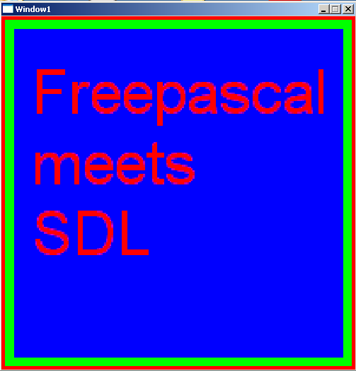
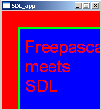
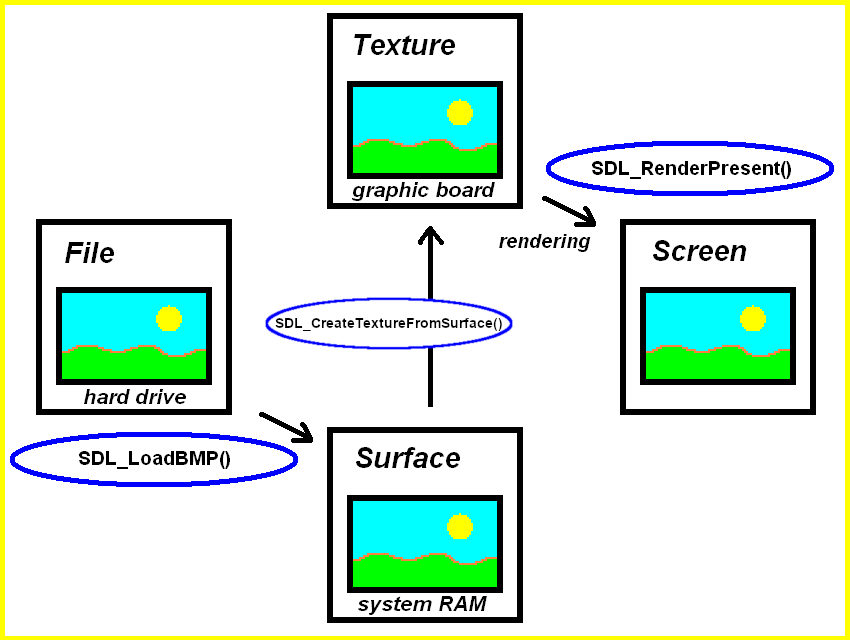
Let’s start on the left in the diagram. The easiest way to get a bitmap (BMP) image file for a game or application ready for usage is to create one in a drawing application. Or use the example bitmap “fpsdl.bmp” we used in the code.
The bmp image file is stored on your hard drive and can be loaded by SDL_LoadBMP function to a SDL2 surface. This SDL2 surface is then transformed into a SDL2 texture by SDL_CreateTextureFromSurface function (whose name is just explaining what is does). And finally this texture is rendered by SDL_RenderPresent, this function we know already.
And now let’s see how it is done in code.
program SDL_LoadingRenderingBMP;

uses SDL2;

var
  sdlWindow1: PSDL_Window;
  sdlRenderer: PSDL_Renderer;
  sdlSurface1: PSDL_Surface;
  sdlTexture1: PSDL_Texture;

begin

  //initilization of video subsystem
  if SDL_Init(SDL_INIT_VIDEO) < 0 then Halt;

  if SDL_CreateWindowAndRenderer(500, 500, SDL_WINDOW_SHOWN, @sdlWindow1, @sdlRenderer) <> 0
    then Halt;

  // create surface from file
  sdlSurface1 := SDL_LoadBMP('fpsdl.bmp');
  if sdlSurface1 = nil then
    Halt;

  // create texture from surface
  sdlTexture1 := SDL_CreateTextureFromSurface(sdlRenderer, sdlSurface1);
  if sdlTexture1 = nil then
    Halt;

  // render texture
  if SDL_RenderCopy(sdlRenderer, sdlTexture1, nil, nil) <> 0 then
    Halt;

  // render to window for 2 seconds
  SDL_RenderPresent(sdlRenderer);
  SDL_Delay(2000);

  // clear memory
  SDL_DestroyTexture(sdlTexture1);
  SDL_FreeSurface(sdlSurface1);
  SDL_DestroyRenderer(sdlRenderer);
  SDL_DestroyWindow (sdlWindow1);

  //closing SDL2
  SDL_Quit;

end.
var
  sdlWindow1: PSDL_Window;
  sdlRenderer: PSDL_Renderer;
  sdlSurface1: PSDL_Surface;
  sdlTexture1: PSDL_Texture;
contains two new variables, namely “sdlSurface1” and “sdlTexture1” of the pointer types PSDL_Surface and PSDL_Texture, respecitvely.
After setting up SDL2, a window and a renderer as known, we find this.
Step 1: Loading the BMP file to a SDL2 Surface
  // create surface from file
  sdlSurface1 := SDL_LoadBMP('fpsdl.bmp');
  if sdlSurface1 = nil then
    Halt;
SDL_LoadBMP(name of bmp image file) does what you expect, it loads the image file and generates a SDL2 surface from it. Attention though, if you just give a file name, it is assumed that the file is found in the same folder as the executing application. Optionally you can also give a full file path, e.g. in Windows something like ‘C:\MyImages\fpsdl.bmp’. The function is declared as
SDL_LoadBMP(_file: PAnsiChar): PSDL_Surface
and return nil on error, e.g. if the file is not found.
Step 2: Creating a SDL2 Texture from the SDL2 Surface
The next step is to get a SDL2 texture. That’s achieve as follows.
  // create texture from surface
  sdlTexture1 := SDL_CreateTextureFromSurface(sdlRenderer, sdlSurface1);
  if sdlTexture1 = nil then
    Halt;
The function to use is SDL_CreateTextureFromSurface(renderer, surface).
It just does what you expect and transforms the SDL2 surface into a SDL2 texture with the help of the given renderer.
Step 3: Prepare the SDL2 Texture to be Rendered
Before actually rendering the texture, we need to copy it to the rendering target (our window) by SDL_RenderCopy(renderer, texture, source rectangle (texture), destination rectangle (rendering target)).
// render texture
  if SDL_RenderCopy(sdlRenderer, sdlTexture1, nil, nil) <> 0 then
    Halt;
So the texture is copied to the rendering target (which is the window). The first nil argument means that we want to copy the whole rectangle. The second nil means that we want to copy to the whole dimensions of the rendering target. Let’s have a closer look at the function.
This will run without any problem, though SDL_CreateTextureFromSurface() will not free the surface created by SDL_LoadBMP(). And you have no handle to free this surface. This creates a memory leak.
This chapter treats some basics you should know to understand the way SDL2 works.
Briefly: The Basics of Graphics Programming
Loading and the movement of images in a game (or other applications) is a major concept in (game) programming. These images are then refered to as sprites, usually. Let’s have a look at a simple example:
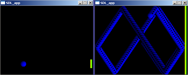
Left: Window is cleared between each new drawn frame. Right: Window is not cleared.
Here are two screenshots from a simple game. The player has to move the yellow-green paddle up- and downwards to prevent the blue ball from getting through to the right side. The game uses two sprites, the blue ball sprite and the yellow-green paddle sprite (see left screenshot). The background color is set to black. The left screenshot is how the game usually appears to the player, here between each frame that got drawn, the former frame has been cleared. The right screenshot demonstrates what happens if the former frame hasn’t been erased before the next one is drawn. – Now it is clearly visible that the sprites are redrawn again and again with sligthly different coordinates, and that is how (game) graphics work (even for the most sophisticated 3d games):
Draw the frame
Show the frame (in a window on screen)
Clear the frame (and go back to step 1)
Briefly: The Relation between Graphic Objects (e.g. Sprites) and Hardware
Actually there are just three locations where these images are stored in your computer system. All images (photo images, drawings, sprites for 2d games, textures for 3d games) are stored on your harddrive somewhere. If you start a photo viewer, a paint program, a 2d game or a 3d game, in all cases the corresponding images need to be loaded from your harddrive to RAM (Random-Access Memory) since displaying and manipulation (e.g. rotation of a photo image by 90°) of images loaded to RAM is much, much faster. Especially for games a fast access to the image data is highly important! And finally there isn’t just one RAM but two, a CPU controlled one located on the motherboard used by every program/application that needs some RAM. The second RAM is located right at your graphic board and controlled by the so-called GPU (graphics processing unit). This is what we want to use if we develop games since it is dedicated, optimized and just hungry for tasks related to fast image processing.
Many games and applications do not only target at common computer systems, but for mobile devices, e.g. smart phones. The principles described are also true for these devices even though there may be differences in detail.
The SDL2 Surface
The SDL2 surface allows you to represent graphic objects like sprites. Every SDL2 surface has a width and height, a pixel format and other properties. Nevertheless, it is a concept which originates from the outdated SDL 1.2 and therefore should not be used anymore. Still, there are reasons why we need to introduce it here. This will be clear soon.
The SDL2 Texture
The SDL2 texture allows you to represent graphic objects just like the SDL2 surface does, although there is a major difference: It is hardware accalerated. So the graphic object is stored in the graphic board’s RAM and any manipulation is done by the graphic board’s GPU.
So as a rule,
always use SDL2 Textures to store your graphic objects (sprites) for SDL 2.0,
then you go for high performance!
Three ways to SDL_Texture
So, how to get a SDL_Texture? In principle there are three ways to create SDL2 textures. For way 2 and 3 the flow diagram may illustrate how it works.
Way 1: From Scratch
You create a SDL_Texture from scratch, so you set a pixel format and texture access format and have to fill in your texture data manually. This is the most sophisticated way and is usually not necessary, unless you work with raw pixel data.
Way 2: The path from the file to the surface, to the texture and to the screen. Way 3: The path rom the file to the texture and to the screen.
Way 2: From SDL2 Surface
2) You have or create a SDL_Surface from an image file first and then you create the SDL_Texture from the SDL_Surface. This way is shown in the diagram but it means two steps.
Way 3: Directly from Image File
3) You create a SDL_Texture from and image file directly. This is shown in the diagram, too. This is the simplest way to create a SDL_Texture.
Any good game has a custom mouse cursor. You may think it would be a good idea to have a SDL2 surface or SDL2 texture and render it as any other sprite right at the mouse position to simulate a mouse cursor. DO NOT do this! The mouse cursor is handled separatly from the other rendering to have it smooth and working in critical situations.
The following code shows how to set up a custom mouse cursor with SDL2 the correct way.
program SDL_MouseCursor;

uses SDL2, SDL2_image;

var
  sdlWindow1: PSDL_Window;
  sdlRenderer: PSDL_Renderer;
  sdlSurface1: PSDL_Surface;
  sdlMouseCursor: PSDL_Cursor;
  sdlEvent: TSDL_Event;
  ExitLoop: Boolean = False;

begin

  //initilization of video subsystem
  if SDL_Init(SDL_INIT_VIDEO) < 0 then Halt;

  SDL_CreateWindowAndRenderer(500, 500, SDL_WINDOW_SHOWN, @sdlWindow1, @sdlRenderer);
  if (sdlWindow1 = nil) or (sdlRenderer = nil) then Halt;

  sdlSurface1 := IMG_Load('Cursor.png' );
  if sdlSurface1 = nil then Halt;

  // create and set new mouse cursor
  sdlMouseCursor := SDL_CreateColorCursor(sdlSurface1, 8, 8);
  if sdlMouseCursor = nil then Halt;

  SDL_SetCursor(sdlMouseCursor);

  while ExitLoop = False do
  begin

    // exit loop if mouse button pressed
    while SDL_PollEvent(@sdlEvent) = 1 do
      if sdlEvent.type_ = SDL_MOUSEBUTTONDOWN then
        ExitLoop := True;

    SDL_SetRenderDrawColor(sdlRenderer, 128, 128, 128, SDL_ALPHA_OPAQUE);
    SDL_RenderClear(sdlRenderer);

    SDL_RenderPresent(sdlRenderer);
    SDL_Delay( 20 );
  end;

  SDL_FreeCursor(sdlMouseCursor);

  SDL_FreeSurface(sdlSurface1);
  SDL_DestroyRenderer(sdlRenderer);
  SDL_DestroyWindow (sdlWindow1);

  //shutting down video subsystem
  SDL_Quit;

end.
To have a custom mouse cursor we need a variable of type PSDL_Cursor. We call it “sdlMouseCursor” here.
  sdlSurface1 := IMG_Load('Cursor.png' );
  if sdlSurface1 = nil then Halt;

  // create and set new mouse cursor
  sdlMouseCursor := SDL_CreateColorCursor(sdlSurface1, 8, 8);
  if sdlMouseCursor = nil then Halt;

  SDL_SetCursor(sdlMouseCursor);
This is the interesting part of the code with regard to creating a custom mouse cursor. The cursor’s image is defined by a SDL surface. We create the SDL surface as known from a previous chapter from a png image file to “sdlSurface1” here.
The custom mouse cursor is created by the following function, which returns nil on error.
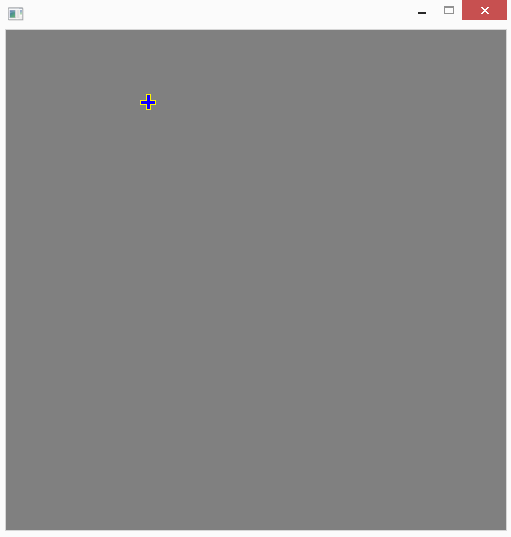
It needs the surface to use as cursor image and two coordinates (hot_x/hot_y) as arguments. They determine where the actual hitting point for this cursor is. Since the example cursor image is of dimensions 16×16 px and represents a cross, the “hot” (hitting) coordiates are (8/8), hence the cross’ center is used for hitting a button or something. In contrast you may imagine a typical arrow shaped mouse cursor, where the hitting point has to be adjusted to be right on the tip of the arrow in the arrow’s image.
If the cursor creation has been successful, it is necessary to set it to be the actual cursor. You may have created many different cursors, so tell SDL which one to use by the following procedure.
SDL_SetCursor(cursor: PSDL_Cursor)
The remaining part of the code is just rendering a 500 by 500 pixels window with a grey (128, 128, 128) background that is updated as long as no mouse button has been pressed.
Finally do not forget to free the mouse cursor by SDL_FreeCursor(mouse cursor) as shown.
This is an SDL 1.2 chapter. SDL 1.2 is obsolete since it has been replaced by SDL 2.0. Unless you have good reasons to stay here you may prefer to go for the modern SDL 2.0 :-).
It is highly recommended that you read the previous Chapter 8. The code from last chapter was used and modified to show how the conversion works. However, I won’t explain twice everything already introduced in Chapter 8. Also I’d like to express here that NeHe Productions’ OpenGL tutorial 06 “Texture Mapping” and the translated (by Dominique Louis) Jedi-SDL file was inspiring me a lot for this chapter.
You need this software:
Software
Version
Source
Description
OpenGL driver
–
–
Usually your graphic card provides the corresponding OpenGL driver and you don’t have to do anything. And if so it is very likely that version 1.1 is fully supported. However if you are one of the few poor people whose graphic card doesn’t support OpenGL, check the graphic card’s manufacturer’s homepage for OpenGL drivers.
Now following the whole code at once as usual. As you will notice many lines are exactly the same as in Chapter 8.
PROGRAM chap8a;
USES CRT, SDL, GL, GLU;

VAR
userkey:CHAR;
screen, picture:pSDL_SURFACE;
h,hh,th,thh:REAL;
ogl_texture:pGLUINT;

BEGIN

//some calculations needed for a regular tetrahedron with side length of 1
h:=SQRT(0.75); //height of equilateral triangle
hh:=h/2;       //half height of equilateral triangle
th:=0.75;      //height of tetrahedron
thh:=th/2;     //half height of tetrahedron

SDL_INIT(SDL_INIT_VIDEO);

SDL_GL_SETATTRIBUTE(SDL_GL_RED_SIZE, 5);
SDL_GL_SETATTRIBUTE(SDL_GL_GREEN_SIZE, 5);
SDL_GL_SETATTRIBUTE(SDL_GL_BLUE_SIZE, 5);
SDL_GL_SETATTRIBUTE(SDL_GL_DEPTH_SIZE, 16);
SDL_GL_SETATTRIBUTE(SDL_GL_DOUBLEBUFFER, 1);

screen:=SDL_SETVIDEOMODE(640, 480, 0, SDL_OPENGL);
IF screen=NIL THEN HALT;

//preparing SDL image
picture:=SDL_LOADBMP('C:\fpsdl256.bmp');
IF picture=NIL THEN HALT;

//preparing OpenGL texture
NEW(ogl_texture);
glGENTEXTURES(1, ogl_texture);
glBINDTEXTURE(GL_TEXTURE_2D, ogl_texture^);
glTEXIMAGE2D(GL_TEXTURE_2D, 0, 3, picture^.w, picture^.h, 0,
             GL_RGB, GL_UNSIGNED_BYTE, picture^.pixels);
glTEXPARAMETERi(GL_TEXTURE_2D, GL_TEXTURE_MIN_FILTER, GL_LINEAR);
glTEXPARAMETERi(GL_TEXTURE_2D, GL_TEXTURE_MAG_FILTER, GL_LINEAR);
SDL_FREESURFACE(picture);


glCLEARCOLOR(0.0, 0.0, 1.0, 0.0);
glVIEWPORT(0,0,640,480);
glMATRIXMODE(GL_PROJECTION);
glLOADIDENTITY;
gluPERSPECTIVE(45.0, 640.0/480.0, 1.0, 3.0);
glMATRIXMODE(GL_MODELVIEW);
glLOADIDENTITY;
glCLEAR(GL_COLOR_BUFFER_BIT);
glENABLE(GL_CULL_FACE);
glTRANSLATEf(0.0, 0.0, -2.0);

REPEAT
SDL_DELAY(50);

glROTATEf(5, 0.0, 1.0, 0.0);
glCLEAR(GL_COLOR_BUFFER_BIT);

//drawing textured face of tetrahedron
glENABLE(GL_TEXTURE_2D);
glBEGIN(GL_TRIANGLES);
    glTEXCOORD2f(2,2);
    glVERTEX3f(thh, 0.0, 0.0);
    glTEXCOORD2f(0,0);
    glVERTEX3f(-thh, hh, 0.0);
    glTEXCOORD2f(0,2);
    glVERTEX3f(-thh, -hh, 0.5);
glEND;
glDISABLE(GL_TEXTURE_2D);

//drawing remaining three untextured faces
glBEGIN(GL_TRIANGLES);
    glCOLOR3f(0.0, 1.0, 1.0);
    glVERTEX3f(thh, 0.0, 0.0);
    glVERTEX3f(-thh, -hh, -0.5);
    glVERTEX3f(-thh, hh, 0.0);

    glCOLOR3f(1.0, 0.0, 1.0);
    glVERTEX3f(thh, 0.0, 0.0);
    glVERTEX3f(-thh, -hh, 0.5);
    glVERTEX3f(-thh, -hh, -0.5);

    glCOLOR3f(1.0, 1.0, 1.0);
    glVERTEX3f(-thh, -hh, 0.5);
    glVERTEX3f(-thh, hh, 0.0);
    glVERTEX3f(-thh, -hh, -0.5);
glEND;

SDL_GL_SWAPBUFFERS;
UNTIL keypressed;

glDELETETEXTURES(1, ogl_texture);
DISPOSE(ogl_texture);
SDL_QUIT;
END.
This code will again draw a tetrahedron which is spinning, as known from Chapter 8. However, this time one face is textured with the “Free Pascal meets SDL” image known from Chapter 3. Now lets go through the code step by step.
PROGRAM chap8a;
USES CRT, SDL, GL, GLU;

VAR
userkey:CHAR;
screen, picture:pSDL_SURFACE;
h,hh,th,thh:REAL;
ogl_texture:pGLUINT;
The program is called “chap8a”. Additionally to the variables defined in the previous chapter there are two new variables. The SDL surface “picture” which will store the SDL image before converting it to an OpenGL texture. ogl_texture is an integer pointer variable (provided by the OpenGL Uitility Library (GLU), so pGLUINT) which is needed to reference to the OpenGL texture we will create from the SDL image.
BEGIN

//some calculations needed for a regular tetrahedron with side length of 1
h:=SQRT(0.75); //height of equilateral triangle
hh:=h/2;       //half height of equilateral triangle
th:=0.75;      //height of tetrahedron
thh:=th/2;     //half height of tetrahedron

SDL_INIT(SDL_INIT_VIDEO);

SDL_GL_SETATTRIBUTE(SDL_GL_RED_SIZE, 5);
SDL_GL_SETATTRIBUTE(SDL_GL_GREEN_SIZE, 5);
SDL_GL_SETATTRIBUTE(SDL_GL_BLUE_SIZE, 5);
SDL_GL_SETATTRIBUTE(SDL_GL_DEPTH_SIZE, 16);
SDL_GL_SETATTRIBUTE(SDL_GL_DOUBLEBUFFER, 1);

screen:=SDL_SETVIDEOMODE(640, 480, 0, SDL_OPENGL);
IF screen=NIL THEN HALT;
The code shown here is discussed in detail in Chapter 8. In short the tetrahedron parameters are calculated, some important OpenGL scene settings are applied and finally the SDL video subsystem is intilized.
//preparing SDL image
picture:=SDL_LOADBMP('C:\fpsdl256.bmp');
IF picture=NIL THEN HALT;
First we should load a simple BMP image to a SDL surface as known from Chapter 3. There are some limitations about the height and length of images if used as OpenGL textures. Their pixel height and pixel length has to be power of 2. So whatever image you use, its height and lengths should fulfill the following equation: f(n) = 2n. So appropriate values are: 2, 4, 8, 16, 32, 64, 128, 256, 512, 1024, 2048,… The height and length don’t have to be of the same size, so an image with height 64 px and width 32 px is perfectly acceptable. This means the image of Chapter 3 with height and length of 200 x 200 px is not acceptable. A new image with 256 x 256 dimensions is therefore provided now:
Free Pascal meets SDL images with 256×256 dimensions
First the pointer “ogl_texture” gets some space. glGENTEXTURES(number of IDs, array of integer pointer) generates one or more OGL integer identifiers for textures. Anyway, we just have one texture, so we just need one texture identifier, therefore we request “1” and ogl_texture should point at it. If we need to identify the texture we just need to call ogl_texture from now on.
glBINDTEXTURE(target, texture) essentially creates a texture object of type: GL_TEXTURE_1D or GL_TEXTURE_2D. Usually textures in 2d and 3d games are two-dimensional, so GL_TEXTURE_2D is a good choice. Now it is clear, ogl_texture will be a 2d texture.
Briefly, glTEXIMAGE2D(target, mipmap level, internal image format, width, height, border, pixel format, pixel type, actual pixel data) creates the actual 2d texture. The target is GL_TEXTURE_2D again since we are looking for creating a 2d texture. The mipmap level should be set to 0 because we wouldn’t want to have a mipmap effect here. A higher number corresponds to the number’s mipmap level, anyway in the example for a number different from 0 there is no image at all finally. The internal image format is RGB because the image is a RGB image, anyway there is a large list of possibilities for this parameter, you should look it up in the internet if you’re interested. The width and height of the image in pixels is received from the SDL image. The border is off (values 0 and 1 are acceptable). The pixel format is RGB, too, so again SDL_RGB is the right choice here. The pixel explains how the pixel data is stored. The pixel data from the SDL image is stored as unsigned byte (GL_UNSIGNED_BYTE). Finally the pixel data pointer of the SDL image is needed. Essentially the SDL image is now transformed to an OGL texture!
Briefly, glTEXPARAMETERi(target, texture parameter, parameter value) allocates a certain value to a specific texture parameter. The possible parameters and values are OGL specific and won’t be treated here in more detail. Anyway, again we are concerned about our 2d texture, so the target is GL_TEXTURE_2D. The parameters to be set are GL_TEXTURE_MIN_FILTER and GL_TEXTURE_MAG_FILTER. They are used to define how to treat textures that have to be drawn to a smaller or larger scale. The routine used for this is specified by GL_LINEAR.
Since the SDL image isn’t needed anymore it can be omitted as known by SDL_FREESURFACE.
This part is completely described in Chapter 8. Nothing has changed for this part. In short, the viewport is set up so that the tetrahedron finally can be seen.
Now the REPEAT..UNTIL loop is entered which is delayed by 50 milliseconds by known SDL_DELAY. Each cycle the the scene gets rotated by 5 degrees around the y-axis by function glROTATEf. More details about this in Chapter 8.
The actual texturing of one of the four triangles of the tetrahedron is now described. Therefore 2d texturing has to be enabled by glENABLE(OGL capability). The capability we would like to enable is defined by GL_TEXTURE_2D.
Just as known from Chapter 8 the triangle mode is started by glBEGIN(geometric primitive type) with GL_TRIANGLES. Instead of a color we now define specific texture coordinates which should be allocated to specific vertices. glTEXCOORD2f(s coordinate, t coordinate) is used to define the coordinate of the texture we then allocate to a specific vertex. By the way, even though the official names of the texture coordinates are s and t, they can be considered as x and y values, which is more common for two-dimensional coordinate systems. The values for s and t are relative, so a value of 1 (= 100%) means the full width or height, independent of the actual width or height (32 x 32, 64 x 64, 128 x 256, …), a value of 2 (= 200%) then corresponds to two times the texture’s width or height. The coordinate (s, t) = (2, 2) is allocated to the vertex with the vertex coordinates (x, y, z) = (thh, 0.0, 0.0). Texture coordinate (0, 0) is allocated to vertex (thh, hh, 0.0). Texture coordinate (0, 2) is allocated to vertex (thh, hh, 0.5). Often this texturing process is compared to papering a wall, and indeed there are similarities. The vertex coordinates are exactly the same as for the first triangle in Chapter 8.
Finally the geometry definition and the texturing mode is finished by glEND and glDISABLE(OGL capability).
The remaining three areas of the triangle are kept as in Chapter 8. Finally the display buffer if swapped after each cycle and the REPEAT..UNTIL loop stopped if a key is pressed in the console.
Last but not least everything has to be free’s and closed as known. Anyway, the texture has to free’d by glDELETETEXTURES(number of textures, texture pointer). Then the pointer can be disposed as known and SDL can be quit.
Again, if you want to learn OpenGL and its capabilities to a more advaced extend you need to read more professional tutorials related to pure OpenGL programming. As a starting point I’d like to mention NeHe Productions’ OpenGL tutorials again, because they are professional and provide example code for JEDI-SDL for several lessons. 🙂
This file contains the source code: chap8a.pas (right click and “save as”)
This file is the executable: chap8a.exe (right click and “save as”)
The final result should look and behave like this: A tetrahedron consisting of three different coloured areas (cyan, magenta and white) and one textured area is spinning slowly around itself. When pressing a key in the console the show quits.
This is an SDL 1.2 chapter. SDL 1.2 is obsolete since it has been replaced by SDL 2.0. Unless you have good reasons to stay here you may prefer to go for the modern SDL 2.0 :-).
In the previous chapter it was shown how to load bitmap images in the bitmap format. You may have wondered if there is a possibility to load other formats than bitmap images. The JEDI-SDL package provides a unit called SDL_IMAGE which exactly is created for this purpose. The following formats you can load according to the unit’s C/C++ documentation: TGA, BMP, PNM, XPM, XCF, PCX, GIF, JPG, TIF, LBM, PNG. I had troubles loading XCF images which is probably due to the fact this format is not standardized.
You need this .dll file to work successfully with the new unit:
This is the corresponding dynamic link library file for unit and image formats.
You should extract the zip-file and get six files. A text file, the important SDL_image.dll and several image format DLLs. Analogous to SDL.dll in chapter 1 you have to copy them to the system32-folder. If you forget this and run the examples below you will get an error with exitcode = 309.
After installation of the unit we now can proceed to the source code.
PROGRAM chap3;
USES SDL, SDL_IMAGE, STRINGS;

CONST
//add the path to your files here
picturepath:PCHAR = 'C:\FPC\2.2.4\my_images\fpsdl.';

VAR
screen:pSDL_SURFACE;
picture: ARRAY[0..2] OF pSDL_SURFACE;
fileextension: ARRAY[0..2] OF PCHAR;
filepath: ARRAY[0..2] OF PCHAR;
i:BYTE;

BEGIN
SDL_INIT(SDL_INIT_VIDEO);
screen:=SDL_SETVIDEOMODE(200,200,32,SDL_SWSURFACE);
IF screen=NIL THEN HALT;


fileextension[0]:='png';
fileextension[1]:='jpg';
fileextension[2]:='tif';

FOR i:=0 TO 2 DO
BEGIN
  filepath[i]:=STRNEW(picturepath);
  filepath[i]:=STRCAT(filepath[i],fileextension[i]);

  picture[i] := IMG_LOAD(filepath[i]);
  IF picture[i]=NIL THEN HALT;

  SDL_BLITSURFACE(picture[i],NIL,screen,NIL);
  SDL_FLIP(screen);
  READLN;
END;

FOR i:=0 TO 2 DO
BEGIN
  SDL_FREESURFACE(picture[i]);
  STRDISPOSE(filepath[i]);
END;
SDL_FREESURFACE(screen);
SDL_QUIT;
END.
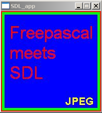
The code shows the same picture known from chapter 3 in three different formats: PNG, JPG and TIF. You should download them (right-click onto each image and save) and put them at a desired location of your hard drive. Don’t worry if the tif image isn’t shown properly in your web browser. Since it isn’t a native web image format most web browsers don’t support it. However you can still download it.
TIF image – usually not supported natively by browsers to be displayed
JPEG images
PNG image
PROGRAM chap3;
USES SDL, SDL_IMAGE, STRINGS;
First we need to include the SDL unit, of course we need also the SDL_IMAGE unit. The STRINGS unit is needed to handle file pathes a simple and short way. The latter unit is not related to the SDL library.
CONST
//add the path to your files here
picturepath:PCHAR = 'C:\FPC\2.2.4\my_images\fpsdl.';

VAR
screen:pSDL_SURFACE;
picture: ARRAY[0..2] OF pSDL_SURFACE;
fileextension: ARRAY[0..2] OF PCHAR;
filepath: ARRAY[0..2] OF PCHAR;
i:BYTE;
Now we define a constant, which contains the absolute path to the image files. The path is C:\FPC\2.2.4\my_images\. Of course you are free to choose any other location. Each file is named “fpsdl.” and the corresponding extension, like “bmp” for bitmap image, “png” for portable network graphics image, and so on. They all lie in the folder my_images.
In the variables part we define the screen surface again and an array of picture surfaces, all of kind pSDL_SURFACE. The screen surface decides what is shown at the display and the picture surfaces will store the images from image files of different formats. Next two arrays for the file extensions of the different image formats (bmp, png,…) and the image file paths are defined and of kind PCHAR. Finally we define the counter variable i.
BEGIN
SDL_INIT(SDL_INIT_VIDEO);
screen:=SDL_SETVIDEOMODE(200,200,32,SDL_SWSURFACE);
IF screen=NIL THEN HALT;


fileextension[0]:='png';
fileextension[1]:='jpg';
fileextension[2]:='tif';
As usual we start by initating the SDL library, defining a 200 x 200 pixels window and check if it was successful. The next part defines the different file extensions we want to use. In this example we will show the ability of SDL_IMAGE to load png, jpg and tif images. Feel free to try out all the other common formats by extending this demo program. Again I’d like to mention that I experienced troubles loading GIMP’s images in XCF format.
FOR i:=0 TO 2 DO
BEGIN
  filepath[i]:=STRNEW(picturepath);
  filepath[i]:=STRCAT(filepath[i],fileextension[i]);

  picture[i] := IMG_LOAD(filepath[i]);
  IF picture[i]=NIL THEN HALT;

  SDL_BLITSURFACE(picture[i],NIL,screen,NIL);
  SDL_FLIP(screen);
  READLN;
END;
The presented loop is the core of this demo program. It shows the preparation of the file locations and names, the creation of the image surfaces and the final blit to the screen surface to display them.
The loop will be cycled three times, once for each file. First we reseve some space on the heap and insert the constant file string by STRNEW. Next we concatenate the file path and the extension by STRCAT. For these operations we needed to include the STRINGS unit. Both commands aren’t related to the SDL library.
Then IMG_LOAD(absolute path/image file) function allows to load image data from image files with many different image formats to a surface. That is the key function of this demo program. However, be aware that the image data loaded to the surface is not compressed anymore and is stored in the usual RGBA format of SDL surfaces. The function returns NIL if it failed.
Since the example pictures have the same dimensions as the screen surface they can be blitted easily by SDL_BLITSURFACE as shown. The screen gets refreshed by SDL_FLIP. Both commands you know from the recent chapter. Finally we wait for the user to press enter after each cycle.
FOR i:=0 TO 2 DO
BEGIN
  SDL_FREESURFACE(picture[i]);
  STRDISPOSE(filepath[i]);
END;
SDL_FREESURFACE(screen);
SDL_QUIT;
END.
Now we have to clean up anything. The loop disposes the picture surfaces and the path strings. Finally the screen surface gets disposed and the SDL environment quit by SDL_QUIT. Except for STRDISPOSE you should remember any command from previous chapters. STRDISPOSE is a command from STRING unit, so again no SDL library related command.
This file contains the source code: chap3a.pas (right click and “save as”).
For this chapter no executable is provided.
Hope you are successful and have fun.
The final result should look and behave like this: First the “Free Pascal meets SDL” image appears in one of the the image formats (different of bitmap). Everytime you press return (or enter) in the console the same image with another format is displayed until the program quits.
This is an SDL 1.2 chapter. SDL 1.2 is obsolete since it has been replaced by SDL 2.0. Unless you have good reasons to stay here you may prefer to go for the modern SDL 2.0 :-).
In the previous chapter it was shown how to draw one pixel to the screen. Of course you could now develop routines to draw primitives from this single pixel manipulation but to make life easier someone (Andreas Schiffler) did this already for you. And furthermore the JEDI project already translated it for you to use it in Free Pascal :).
Maybe you remember the Turbo Pascal GRAPH unit which allowed to draw simple primitives like lines, squares, rectangles, circles, polygons and so on. Exactly this part is now fulfilled by the SDL_GFX unit in a SDL environment. So from now on you can also draw sprites directly to the surfaces and don’t have to draw them externally in a painting program. If you choose to draw sprites directly with this set of primitives or create them externally depends on your needs and preferences. Of course you can combine both features, load up an image first, then manipulate it further by the features shown in this chapter.
As an example you could imagine a game where you have game objects of the same type for each player which only differ by the same coloured elements. You now could create several object images with the possible different colours externally. However, if you want to provide 100 different colours you have to load up the object’s image 100 hundred times into your painting program, colour it, save it. You need 100 times the colour images space on hard disk. – With the provided functions you could just create ONE image of the units with a “wild card colour”, let’s say white. Now you just have to write a function which recognizes white areas on the image and colour it in 100 different colours, save it to hard disk (same space usage as first method) or in heap (no further hard disk space is needed!). Especially useful is the SDL_GFX unit if the white areas are of shape rectangle, circle, polygon or just a single pixel.
Before starting with SDL_GFX be aware that it is distributed by a third party developer, Andreas Schiffler. Unfortunately he is not distributing the pre-compiled shared library (DLL file) but instead he provides the source code only. So you are in need of compiling this file yourself or download the compiled SDL_gfx.dll file (zipped) (version 2.0.19) I compiled for you. The source code is written in C++ so you can’t use the Free Pascal compiler to do the compilation yourself. In the first part of this chapter I will deal with the compilation of your own DLL. The provided a pre-compiled SDL_gfx.dll (zipped) was compiled by me under 32 Bit Windows XP Professional on an AMD processor and usage might cause problems for 64 Bit systems and differing operating systems and processors. Furthermore it might be outdated, it’s version 2.0.19. In all these cases you should really consider to compile your own DLL file if the provided file isn’t working for you. If you use the pre-compiled DLL file you can skip the compilation procedure, just go on reading after the 15 step procedure for compilation below.
For compilation we need several things. We need a free C++ compiler to compile the DLL file from the source code. Of course we need the source code of SDL_GFX itself. Furthermore we need the SDL Development Library for Windows. The following table shows the names of the most recent files and their location.
SDL development library. Look for “SDL 1.2” in the menu, then for the development libraries.
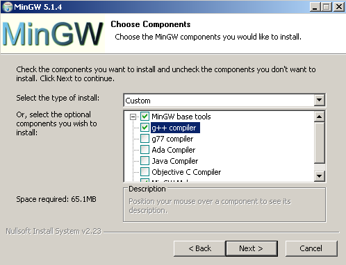
1) First of all, get the MinGW C++ compiler installed. Make sure you check the g++ compiler, which is actually the C++ compiler we are looking for! The other compilers you can leave unchecked. See the picture below.
2) Extract the Development Library of SDL (SDL-devel-1.2.14-mingw32.tar.gz or newer).
3) Among other things there should be one folder called “lib” within the newly created folder of step 2. Copy the complete content of folder “lib” (3 files) into a folder also named “lib” in the MinGW directory. Make sure only to copy these three files, not the folder “lib” itself.
4) There is also a folder “include” in the extracted SDL Development Library folder. It contains one further folder called “SDL” (contains 34 files). This time copy this folder “SDL” as a whole into the “include” folder of the MinGW installation.
5) Now MinGW is fully prepared for the compiling of SDL_GFX.
6) Extract now the source code of SDL_GFX (SDL_gfx-2.0.22.tar.gz or newer).
7) Within the newly created folder you find a folder called “Other Builds”. Enter this folder. Within this folder you will find several zip files.
8) Extract file “mingw.zip”. This creates a new folder “mingw” and contains exact two files, “Makefile” and “README”.
9) Copy “Makefile” into the root folder of SDL_gfx.
10) Before using this makefile some changes have to be applied. The following script shows the first few lines of the makefile. The bold red printed parts have to be changed according to your needs. [REMARK: Now the lines are marked.]
11) “c:/dev/local” has to be the path to the MinGW root folder [Line 5]. Remove flag “-DWIN32” [Line 10] and change the include flag/path to the corresponding (MinGW root folder)/include/SDL [Line 10, “-I(your path)/include/SDL”]. By the way, make sure to use slashes “/” instead of backslashes “\” to separate folders. Also give the library path as (MinGW root folder)/lib [Line 11, “-L(your path)/lib”]. Now save this makefile.
12) To compile the DLL file now, open the command window of Windows by using Start–>Run…, there type “cmd” and the n “OK”. A new “DOS-like” window will pop up.
12) Change the directory to the SDL_GFX root folder by using the DOS commands “cd (foldername)” and “cd..” to enter or leave a folder.
13) Now just give the full path to the MinGW make program located at “(MinGW root folder)\bin\mingw32-make”. Now press enter and see how your DLL file gets compiled.
14) If everything worked well you find a brand new SDL_gfx.dll in your SDL_GFX root folder.
15) Copy this file to your WINDOWS\system32 folder or to the folder where the application is located which is using SDL_GFX.
Now, since compilation is finished (or you skipped the compilation procedure) just a short hint about the licensing, SDL_GFX is licensed under the LGPL, which essentially means you can also use it in proprietary software.
Before proceeding make sure Free Pascal finds the SDL and SDL_GFX units (Options–>Directories…), however, if you installed a recent binary Free Pascal package you don’t have to care about this. Free Pascal then is already well configured to work with SDL and SDL_GFX.
Now we can proceed to the source code. Here is the full source code of the example program. It will rotate and at the same time zoom an image constantly and additionally draw some primitives to the screen.
PROGRAM chap4a;
USES SDL, SDL_GFX, CRT;

CONST
x_array:ARRAY[0..5] OF SINT16 = (50, 150, 250, 250, 150, 50);
y_array:ARRAY[0..5] OF SINT16 = (100, 50, 100, 200, 250, 200);

VAR
screen,original_image,modified_image:pSDL_SURFACE;
angle_value, zoom_value:DOUBLE;
framerate:pFPSMANAGER;
calc_width, calc_height:LONGINT;

BEGIN
SDL_INIT(SDL_INIT_VIDEO);
screen:=SDL_SETVIDEOMODE(400,400,32,SDL_SWSURFACE);
IF screen=NIL THEN HALT;

original_image:=SDL_LOADBMP('C:\FPC\2.2.2\bin\i386-win32\test\fpsdl.bmp');
IF original_image=NIL THEN HALT;

NEW(modified_image);
angle_value:=0.0;
zoom_value:=0.0;

NEW(framerate);
SDL_INITFRAMERATE(framerate);
SDL_SETFRAMERATE(framerate, 30);

REPEAT
  angle_value:=angle_value+1.0;
  zoom_value:=zoom_value+0.05;
  IF angle_value>=359 THEN angle_value:=0.0;
  IF zoom_value>=2.0 THEN zoom_value:=0.0;

  ROTOZOOMSURFACESIZE(400, 400, angle_value, zoom_value, calc_width, calc_height);
  WRITELN('Width: ',calc_width,' Height: ',calc_height);
  modified_image:=ROTOZOOMSURFACE(original_image, angle_value, zoom_value, 1);

  CIRCLECOLOR(screen, 200, 200, 100, $FFFF00FF);
  FILLEDCIRCLECOLOR(screen, 200, 200, 50, $00FF00FF);
  ELLIPSECOLOR(screen, 200, 200, 175, 75, $00FFFFFF);
  FILLEDPIECOLOR(screen, 200, 200, 110, 10, 100, $FF0000FF);
  POLYGONCOLOR(screen, @x_array[0], @y_array[0], 6, $000000FF);
  BEZIERCOLOR(screen, @x_array[3], @y_array[3], 3, 2, $FFFFFFFF);


  SDL_BLITSURFACE(modified_image,NIL,screen,NIL);
  SDL_FLIP(screen);

  SDL_FRAMERATEDELAY(framerate);
UNTIL keypressed;

SDL_FREESURFACE(original_image);
SDL_FREESURFACE(modified_image);
SDL_FREESURFACE(screen);

DISPOSE(framerate);

SDL_QUIT;
END.
Now that you know the whole code, let’s discuss it step by step.
PROGRAM chap4a;
USES SDL, SDL_GFX, CRT;

CONST
x_array:ARRAY[0..5] OF SINT16 = (50, 150, 250, 250, 150, 50);
y_array:ARRAY[0..5] OF SINT16 = (100, 50, 100, 200, 250, 200);

VAR
screen,original_image,modified_image:pSDL_SURFACE;
angle_value, zoom_value:DOUBLE;
framerate:pFPSMANAGER;
calc_width, calc_height:LONGINT;
The program is called “chap4a” and uses the known units SDL and CRT (CRT for easy recognition of user pressing a key on the keyboard). Additionally the new unit SDL_GFX has to be included here. The latter unit provides the functionality described below.
There is a constant block defining two constant arrays “x_array” and “y_array” containing six elements of SINT16 (16 bit signed integer) corresponding to six x and y values. These will be needed later to define a polygon and a Bézier curve.
Three surface variables are defined. The “screen” variable represents the screen surface. The “original_image” surface stores an image, which then is manipulated (rotation and zooming) and the result is stored in the “modified_image” surface. The float number variables “angle_value” and “zoom_value” are storing a certain rotation angle and a zoom factor. Finally variable “framerate” is defined as a framerate manager variable pFPSMANAGER which is new and provided by SDL_GFX. This helpful tool is discussed in much detail later. Finally two variables “calc_width” and “calc_height” are defined and have to be of type LONGINT. They will store the estimated new size of the surface after rotation and zooming.
BEGIN
SDL_INIT(SDL_INIT_VIDEO);
screen:=SDL_SETVIDEOMODE(400,400,32,SDL_SWSURFACE);
IF screen=NIL THEN HALT;

original_image:=SDL_LOADBMP('C:\FPC\2.2.2\bin\i386-win32\test\fpsdl.bmp');
IF original_image=NIL THEN HALT;

NEW(modified_image);
angle_value:=0.0;
zoom_value:=0.0;
The “screen” surface is initialized as known from previous chapters with 400 x 400 px. The “Free Pascal-meets-SDL” bitmap image from Chapter 3 is loaded to the surface variable “original_image”. For those who don’t remember the image, here it is again:
download (right click and “save as”)
Notice, this image has 200 x 200 dimension. The “original_surface” surface will be the source for any manipulation. The second surface “modified_image” gets some space allocated and is ready for usage. However until now it stays empty. The rotation angle and the zoom factor are set to zero.
The framerate manager “framerate” gets some space and is initialized by PROCEDURE SDL_INITFRAMERATE(manager:PFPSmanager). Then the framerate is set in Hz (Hertz) by FUNCTION SDL_SETFRAMERATE(manager:PFPSmanager; rate:INTEGER):INTEGER which returns 0 on success and -1 if something is wrong. The default value is 30 Hz. It is also stored in flag FPS_DEFAULT. Additionally there are FPS_UPPER_LIMIT and FPS_LOWER_LIMIT which correspond to 200 and 1 Hz. Not shown in the example code is FUNCTION SDL_GETFRAMERATE(manager:PFPSMANAGER):INTEGER which will just return the set FPS value, however it will not return the real framerate. Even if the framerate dropped to 1 Hz it will return 30 Hz since this is the set value.
Well, some notes about the framerate: The framerate is usually a value indicating how many frames per second are drawn and shown at the screen. 30 Hz means there are 30 frames drawn to the screen within one second. Often the frequency if abbreviated by FPS meaning Frames Per Second, thus 30 FPS is the same as 30 Hz. If you perform many drawing operation or costly drawing operations (especially 3d applications know this) then it might be that the framerate drops because the system (processor and/or graphic hardware) isn’t capable of drawing fast enough to keep 30 frames per second.
So what about the framerate manager, how does it help? In simple programs the SDL_DELAY(delay in milli seconds) function is used to control the framerate if placed in the rendering loop (the loop which flips the scene to the screen surface). Assuming you set is to 33, so SDL_DELAY(33) it means every 33 ms one frame is drawn, this means approximately 30 frames are drawn within one second! Thus the framerate is 30 Hz here as well. However this only applies if you assume that the drawing itself doesn’t need time, which is a good approximation for simple applications and simple scenes. When drawing more complex scenes the drawing itself will take some milli seconds or even more time, the SDL_DELAY function will just add its delay time, so this leads to a remarkable delay. In contrast a framerate manager recognizes that the framerate dropped and will skip the delay time to keep the framerate at 30 Hz (or whatever value is set). Additionally the framerate manager is keeping the actual framerate more accurately at the framerate, in the contrary SDL_DELAY is quite inaccurate.
REPEAT
  angle_value:=angle_value+1.0;
  zoom_value:=zoom_value+0.05;
  IF angle_value>=359 THEN angle_value:=0.0;
  IF zoom_value>=2.0 THEN zoom_value:=0.0;

  ROTOZOOMSURFACESIZE(400, 400, angle_value, zoom_value, calc_width, calc_height);
  WRITELN('Width: ',calc_width,' Height: ',calc_height);
  modified_image:=ROTOZOOMSURFACE(original_image, angle_value, zoom_value, 1);
Now the rendering loop is entered. Every cycle the rotation angle is increased by 1.0 degree. Also the zoom factor is increased by 0.05 every cycle. A zoom factor of 1.0 means no change of the picture. Values smaller than 1.0 mean shrinkage of the image, values larger than 1.0 mean enlargement of the image. A value of 0.5 and 2.0 mean half the size and double the size of the original image respectively. The two IF clauses ensure that the value of “angle_value” is restored to 0 (equals 360) degree (no rotation), if the image is rotated by 259 degree. If the image got zoomed to twice its original size, “zoom_value” gets restored to 0.0.
PROCEDURE ROTOZOOMSURFACESIZE(width:INTEGER; height:INTEGER; angle:DOUBLE; zoom:DOUBLE; VAR dstwidth:INTEGER; VAR dstheight:INTEGER) calculates the new surface size after rotation and zooming. The first two parameters are the width and height of the initial surface (in our example the image/surface has 200 x 200 dimension). The next two parameters expect the rotation and zoom values (in our example they are stored in “rotation_angle” and “zoom_angle”). The last two parameters store the return values. The results will be returned to “calc_width” and “calc_height” in our example. They are written to the screen. Now one of the most amazing functions of the SDL_GFX unit is introduced. It allows the rotation and zooming of an image. In FUNCTION ROTOZOOMSURFACE(src:pSDL_SURFACE; angle:DOUBLE; zoom:DOUBLE; smooth:INTEGER):pSDL_SURFACE you give the source surface first, which is the surface with the original image in our case, then the angle and zoom factor which we discussed right before and finally if antialiasing should be performed. Antialiasing means to smooth edges. 0 means no antialiasing, 1 means antialiasing, well, also two flags you could use, SMOOTHING_OFF and SMOOTHING_ON. (However I experienced that antialiasing didn’t work out even though a 32 bit surface is used which is necessary to perform antialiasing as the author stated.)
There are some accompied functions not demonstrated in the example code which should be mentioned now. FUNCTION ZOOMSURFACE(src:pSDL_SURFACE; zoomx:DOUBLE; zoomy:DOUBLE; smooth:INTEGER):pSDL_SURFACE zooms only without rotation but zooming in x direction and y direction can be set independently. FUNCTION ROTOZOOMSURFACEXY(src:pSDL_SURFACE; angle:DOUBLE; zoomx:DOUBLE; zoomy:DOUBLE; smooth:INTEGER):pSDL_SURFACE is the same function as before but with rotation additionally. For both of these functions also corresponding procedures exist which return the size of the newly created surfaces. Thay are PROCEDURE ZOOMSURFACESIZE(width:INTEGER; height:INTEGER; zoomx:DOUBLE; zoomy:DOUBLE; VAR dstwidth:INTEGER; VAR dstheight:INTEGER) and PROCEDURE ROTOZOOMSURFACEXYSIZE(width:INTEGER; height:INTEGER; angle:DOUBLE; zoomx:DOUBLE; zoomy:DOUBLE; VAR dstwidth:INTEGER; VAR dstheight:INTEGER). They work the very same way as demonstrated in the example code.
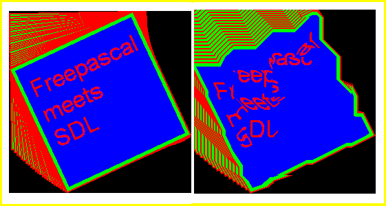
It is very important to keep in mind that every manipulating procedure (rotation and zooming) is distorting the image information. So the number of manipulations should be keep as small as possible. In the example every cycle of the loop the original image gets manipulated exactly two times. It gets rotated once and zoomed once. Instead of this you could also implement a recursive solution, namely rotating the original image in the first cycle by one degree, take the resulting image and rotate it in the second cycle again by one degree, and so on. Let’s check for the result after 25 cycles, in fact both methods rotated the image by 25 degree, but well, the quality is remarkable different. And this neglecting the zooming which has an even worse impact on quality if implemented recursively. The following drawing will illustrate what the results will look like. On the left the rotation of the original image by 25 degree once, on the right the rotation of the same image 25 times by one degree.
Left: Rotation once by 25 degree; Right: 25 Rotations by one degree
The loss of information with each cycle will add up for each manipulation leading to ugly results like the right one. Compare this to the left image where no loss of information is noticable.
As promised SDL_GFX is able to draw a lot of primitives. The primitives shown in the example code are just a few of them. The principle of implementing them is demonstrated anyway. The table below gives the complete list of primitives you can use. Most of the functions are intuitive, so a circle is defined by its position (x/y values), its radius r and its colour. The same applies for a filled circle. An ellipse is defined by its position (x/y values), its horizontal and vertical axes rx and ry, and its colour.
Especially polygon and Bézier curve calls may be not so intuitive. The polygon function is function POLYGONCOLOR(dst:pSDL_SURFACE; const vx:pSINT16; const vy:pSINT16; n:INTEGER; color:UINT32):INTEGER and the Bézier curve function is function BEZIERCOLOR(dst:pSDL_SURFACE; const vx:pSINT16; const vy :pSINT16; n:INTEGER; s:INTEGER; color:UINT32):INTEGER. As for all the other functions you define the surface first onto which you would like to draw these primitives. The next parameters expect a pointer (pSINT16) to an array of x values of type SINT16 (16 bit unsigned integer) and an array of y values of the same type. This is achieved by the @ operator at the first and fourth element of the arrays respectivly. These vectors were defined initially in the constant block, you should remember. The next parameter n is the number of points the polygon has or the number of reference points the Bézier curve has. If the arrays contain six elements, n should be six as well. Since in the case of the Bézier curve only the last three elements are of interest (at least in our example), n has to be three and the resulting curve is of order four (quadratic Bézier curve). The s value defines the smoothness of the curve. The higher s the higher the smoothness.
Some general information about these primitive functions: All functions presented here have the same suffix …COLOR. This means that the last parameter expects the colour you desire in hexadecimal form, $RRGGBBAA. The hexadecimal digit 00 corresponds to decimal digit 0, and hexadecimal digit FF corresponds to decimal digit 255. All of these function are accompanied by a function with the suffix …RGBA instead of …COLOR. Here, all parameters are the same except from the colour parameter, instead of ONE colour code in hexadecimal form, you enter four parameters r, g, b, a (red, green, blue, alpha/transparency). For example instead of $FF0000FF you put 255, 0, 0, 255. All functions return 0 as INTEGER value on success.
In many cases there are further accompanied functions with the prefix aa. This means the very same function with the same parameter list but the result is antialiased. For many functions furthermore the prefix filled is possible as shown for the circle in the example code. Also here the parameter list is completely the same but the resulting primitive is filled with the given colour.
  SDL_BLITSURFACE(modified_image,NIL,screen,NIL);
  SDL_FLIP(screen);

  SDL_FRAMERATEDELAY(framerate);
UNTIL keypressed;
Primitive
Definition
Description
Of all functions two types exist: …Color and …RGBA. They are in fact equal and differ only in the way you put in the colour information. For …Color functions there is the color:Uint32 argument where you put in the colour code in hexadecimal form, e.g. $FF0000FF for red without transparency. For …RGBA functions there are four arguments r:Uint8; g:Uint8; b:Uint8; a:Uint8 where you enter 255; 0; 0; 255 for red without transparency.
Functions with the prefix aa are equal to the functions without this prefix but are printing antialiased primitives. Functions with the prefix filled are equal to the functions without this prefix but the enclosed area of the primitive is filled with the given colour. Antialiased primitives are never filled and vice versa.
All functions return 0 as INTEGER on success.
Pixel (Dot)
function pixelColor( dst : PSDL_Surface; x : Sint16; y : Sint16; color : Uint32 ) : integer
Draws one pixel at position (x/y) in the given colour.
function pixelRGBA( dst : PSDL_Surface; x : Sint16; y : Sint16; r : Uint8; g : Uint8; b : Uint8; a : Uint8 ) : integer
Line
function hlineColor( dst : PSDL_Surface; x1: Sint16; x2 : Sint16; y : Sint16; color : Uint32 ) : integer
Draws a horizontal line from x1 to x2 at height y in the given colour.
function hlineRGBA( dst : PSDL_Surface; x1: Sint16; x2 : Sint16; y : Sint16; r : Uint8; g : Uint8; b : Uint8; a : Uint8 ) : integer
function vlineColor( dst : PSDL_Surface; x : Sint16; y1 : Sint16; y2 : Sint16; color : Uint32 ) : integer
Draws a vertical line at position x from y1 to y2 in the given colour.
function vlineRGBA( dst : PSDL_Surface; x : Sint16; y1 : Sint16; y2 : Sint16; r : Uint8; g : Uint8; b : Uint8; a : Uint8 ) : integer
function boxRGBA( dst : PSDL_Surface; x1 : Sint16; y1 : Sint16; x2 : Sint16;
y2 : Sint16; r : Uint8; g : Uint8; b : Uint8; a : Uint8 ) : integer
Circle
function circleColor( dst : PSDL_Surface; x : Sint16; y : Sint16; r : Sint16; color : Uint32 ) : integer
Draws a circle with the center at position (x/y) and the radius r in the given colour.
function circleRGBA( dst : PSDL_Surface; x : Sint16; y : Sint16; rad : Sint16; r : Uint8; g : Uint8; b : Uint8; a : Uint8 ) : integer
function aacircleColor( dst : PSDL_Surface; x : Sint16; y : Sint16; r : Sint16; color : Uint32 ) : integer
function aacircleRGBA( dst : PSDL_Surface; x : Sint16; y : Sint16;
rad : Sint16; r : Uint8; g : Uint8; b : Uint8; a : Uint8 ) : integer
function filledCircleColor( dst : PSDL_Surface; x : Sint16; y : Sint16; r : Sint16; color : Uint32 ) : integer
function filledCircleRGBA( dst : PSDL_Surface; x : Sint16; y : Sint16;
rad : Sint16; r : Uint8; g : Uint8; b : Uint8; a : Uint8 ) : integer
Pie
function pieColor( dst : PSDL_Surface; x : Sint16; y : Sint16; rad : Sint16;
start : Sint16; finish : Sint16; color : Uint32 ) : integer
Draws a pie chart with the pie’s edge being at position (x/y) with the radius rad. “start” and “finish” define the arc length of the pie in degree. If “start” is 0 then the pie starts at the right (east) side of a circle. To start at the top, “start” should be 270 or -90. If “start” is 0 and “finish” is 90, you get one quarter of a circle.
function pieRGBA( dst : PSDL_Surface; x : Sint16; y : Sint16; rad : Sint16;
start : Sint16; finish : Sint16; r : Uint8; g : Uint8; b : Uint8; a : Uint8 ) : integer
function filledPieColor( dst : PSDL_Surface; x : Sint16; y : Sint16; rad : Sint16;
start : Sint16; finish : Sint16; color : Uint32 ) : integer
function filledPieRGBA( dst : PSDL_Surface; x : Sint16; y : Sint16; rad : Sint16;
start : Sint16; finish : Sint16; r : Uint8; g : Uint8; b : Uint8; a : Uint8 ) : integer
Ellipse
function ellipseColor( dst : PSDL_Surface; x : Sint16; y : Sint16; rx : Sint16; ry : Sint16; color : Uint32 ) : integer
Draws an ellipse with its center at position (x/y) and the two radii rx and ry for its horizontal and vertical axes in the given colour.
function ellipseRGBA( dst : PSDL_Surface; x : Sint16; y : Sint16;
rx : Sint16; ry : Sint16; r : Uint8; g : Uint8; b : Uint8; a : Uint8 ) : integer
function aaellipseColor( dst : PSDL_Surface; xc : Sint16; yc : Sint16; rx : Sint16; ry : Sint16; color : Uint32 ) : integer
function aaellipseRGBA( dst : PSDL_Surface; x : Sint16; y : Sint16;
rx : Sint16; ry : Sint16; r : Uint8; g : Uint8; b : Uint8; a : Uint8 ) : integer
function filledEllipseColor( dst : PSDL_Surface; x : Sint16; y : Sint16; rx : Sint16; ry : Sint16; color : Uint32 ) : integer
function filledEllipseRGBA( dst : PSDL_Surface; x : Sint16; y : Sint16;
rx : Sint16; ry : Sint16; r : Uint8; g : Uint8; b : Uint8; a : Uint8 ) : integer
function filledTrigonRGBA( dst : PSDL_Surface; x1 : Sint16; y1 : Sint16; x2 : Sint16; y2 : Sint16; x3 : Sint16; y3 : Sint16;
r : Uint8; g : Uint8; b : Uint8; a : Uint8 ) : integer
function polygonColor( dst : PSDL_Surface; const vx : PSint16; const vy : PSint16; n : integer; color : Uint32 ) : integer
Draws a polygon with x values from array of SINT16 in vx. y values are from array of SINT16 in vy. n is the number of edges/points the polygon has.
function polygonRGBA( dst : PSDL_Surface; const vx : PSint16; const vy : PSint16;
n : integer; r : Uint8; g : Uint8; b : Uint8; a : Uint8 ) : integer
function aapolygonColor( dst : PSDL_Surface; const vx : PSint16; const vy : PSint16; n : integer; color : Uint32 ) : integer
function aapolygonRGBA( dst : PSDL_Surface; const vx : PSint16; const vy : PSint16;
n : integer; r : Uint8; g : Uint8; b : Uint8; a : Uint8 ) : integer
function filledPolygonColor( dst : PSDL_Surface; const vx : PSint16; const vy : PSint16; n : integer; color : Uint32 ) : integer
function filledPolygonRGBA( dst : PSDL_Surface; const vx : PSint16;
const vy : PSint16; n : integer; r : Uint8; g : Uint8; b : Uint8; a : Uint8 ) : integer
Bézier curve
function bezierColor( dst : PSDL_Surface; const vx : PSint16; const vy : PSint16; n : integer; s : integer; color : Uint32 ) : integer
Draws a Bézier curve of any order. n is the number of points, well n+1 is the order of the curve then. The x and y values are from arrays of SINT16. The higher value s the smoother the curve gets. s should be 2 at least.
function bezierRGBA( dst : PSDL_Surface; const vx : PSint16; const vy : PSint16;
n : integer; s : integer; r : Uint8; g : Uint8; b : Uint8; a : Uint8 ) : integer
SDL_BLITSURFACE(modified_image,NIL,screen,NIL);
SDL_FLIP(screen);
SDL_FRAMERATEDELAY(framerate);
UNTIL keypressed;
Nothing really new here. The “modified_image” surface with the rotated, zoomed image and the primitives is blitted to the screen surface. The result is flipped to the screen. Then the extensivly discussed framerate manager decides by procedure SDL_FRAMERATEDELAY(manager:PFPSMANAGER) how long actually to wait until the loop is repeated. This procedure replaces the common SDL_DELAY command. The loop is stopped when the user presses any key.
Finally all the used surfaces are free’d and the framerate manager is disposed. SDL is quit and the program finished.
This file contains the source code: chap4a.pas (right click and “save as”)
This file is the executable: chap4a.exe (right click and “save as”)
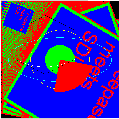
The final result should look and behave like this: The image fpsdl.bmp is rotated and zoomed continouisly and some primitives (circle, filled circle, ellipse, pie, hexagon, Bézier curve) are drawn onto the image. If you use the pre-compiled exe file make sure to have the image copied to c:\.
[Downloads transferred from old website]
SDL_gfx.dll; The pre-compiled SDL_gfx.dll (Version 2.0.19) for chapter 4a.
SDL_gfx-2.0.19.tar.gz; For license reasons here you can download the source code to compile the SDL_gfx.dll for chapter 4a. However, the most recent version for compilation you will find on the authour’s page.
This is an SDL 1.2 chapter. SDL 1.2 is obsolete since it has been replaced by SDL 2.0. Unless you have good reasons to stay here you may prefer to go for the modern SDL 2.0 :-).
Working with the video subsystem assumes that you understand the concept behind. In SDL the surface is a central concept. Surfaces are parts of the memory (RAM) where an image is saved. Every surface can have its own size (pixels x pixels, e.g. 640 x 480) and properties (e.g. with or without alpha channel for transparency effects). You can copy(=blit) a part or the whole surface to any other surface. This is the second very important concept and is called blitting
There is a special surface: the display surface. Everything that got blit to this surface gets displayed on the physical screen (monitor) after refreshing (SDL_FLIP(…), SDL_UPDATERECT(…))!
For example in demo03.pas / demo03.exe from a modified SDL4Free Pascal demo file the ball, the paddle and the black background (display surface background color) are surfaces. The ball and the paddle are copied(=blitted) onto the black screen surface again and again slightly moved up. So the ball and the paddle seem to move.
If you think carefully about this or check the source code you will notice that between every blitting process the ball and paddle of the previous frame have to be overdrawn by black rectangles erasing them (left), otherwise the result would look like the right example.
So our task is to create a display surface. Furthermore we need a surface that contains a picture. Eventually the picture should get copied onto the display surface. After that the picture should be displayed at the physical screen. The whole code looks like this.
PROGRAM chap3;
USES SDL, CRT;
VAR
screen,picture:pSDL_SURFACE;
source_rect,destination_rect:pSDL_RECT;

BEGIN
SDL_INIT(SDL_INIT_VIDEO);
screen:=SDL_SETVIDEOMODE(200,200,32,SDL_SWSURFACE);
IF screen=NIL THEN HALT;

picture:=SDL_LOADBMP('C:\FPC\2.0.4\bin\i386-win32\test\fpsdl.bmp');
IF picture=NIL THEN HALT;

NEW(source_rect);
source_rect^.x:=0;
source_rect^.y:=0;
source_rect^.w:=200;
source_rect^.h:=200;
NEW(destination_rect);
destination_rect^.x:=0;
destination_rect^.y:=0;
destination_rect^.w:=200;
destination_rect^.h:=200;

REPEAT
  SDL_BLITSURFACE(picture,source_rect,screen,destination_rect);
  SDL_FLIP(screen);
  DEC(source_rect^.w);
  DEC(source_rect^.h);
  INC(destination_rect^.x);
  INC(destination_rect^.y);
  DEC(destination_rect^.w);
  DEC(destination_rect^.h);
  SDL_DELAY(30);
  IF source_rect^.w=1 THEN
  BEGIN
    source_rect^.x:=0;
    source_rect^.y:=0;
    source_rect^.w:=200;
    source_rect^.h:=200;
    destination_rect^.x:=0;
    destination_rect^.y:=0;
    destination_rect^.w:=200;
    destination_rect^.h:=200;
  END;
UNTIL keypressed;

SDL_FREESURFACE(picture);
SDL_FREESURFACE(screen);

DISPOSE(source_rect);
DISPOSE(destination_rect);

SDL_QUIT;
END.
Now we need a command to create a display surface. Creating a surface is always introduced by setting up a surface variable. The variable type is pSDL_SURFACE and is kind of pointer type as indicated by the “p” in front of it. pSDL_SURFACE is used for the display surface and any other surface.
PROGRAM chap3;
USES SDL, CRT;
VAR
screen,picture:pSDL_SURFACE;
source_rect,destination_rect:pSDL_RECT;
The first line determines the program name. Then we again define that we want to use the SDL unit to be loaded. We introduce the CRT unit which is a basic Pascal unit (check Chapter 2 for more details on CRT). It is needed to detect in a simple way when the user presses a key to stop the repeat/until loop (in Chapter 6 we will learn how SDL handles keyboard interactions). Finally we decide to set up two surfaces. The display surface (screen) has some special properties that can be set. The surface “picture” will store the picutre from a bitmap file. The two variabes “source_rect” and “destination_rect” will be used later to define some rectangles. More details on this later in this chapter.
After using surfaces you have to clean the memory if you don’t need them anymore. Therefore you use the procedure SDL_FREESURFACE(surface:pSDL_Surface) which you have to call for any surface (including the display surface).
BEGIN
SDL_INIT(SDL_INIT_VIDEO);
screen:=SDL_SETVIDEOMODE(200,200,32,SDL_SWSURFACE);
IF screen=NIL THEN HALT;
After initializing SDL as seen in the previous chapter already we now go into details on the set up of the display surface. The function to define a surface as display surface is SDL_SETVIDEOMODE(width,height,bpp:INTEGER; flags:UInt32):pSDL_SURFACE and returns NIL if an errors occurs meaning no pointer for a display surface could be set up. The first parameter determines the width, the second one the height in pixels. The third parameter determines the colordepth in bits (32 bit for now) and the last one the appearance (windowed or fullscreen, with or without border) and space handling (software or hardware memory used). The first three parameters are of integer type, the last one UInt32 (check Chapter 2 for more details on UInt32). There are some very interesting flags. The chosen one, SDL_SWSURFACE, is used if you want to store the surface in system memory (RAM). Alternatively you could chose SDL_HWSURFACE what causes a storage in video memory. Both will create windowed screens that cannot be resized. SDL_NOFRAME would create a windowed screen without a frame. Eventually there is SDL_FULLSCREEN which leads to a fullscreen display. You also can combine several flags by “OR” keyword. So setting up this same window without a frame would be screen:=SDL_SETVIDEOMODE(200,200,32,SDL_SWSURFACE OR SDL_NOFRAME).
Direct loading of a picture to the screen surface is impossible so it is necessary to create another surface that contains the picture. Fourtunately there is a function called SDL_LOADBMP(filename:pCHAR):pSDL_SURFACE. Make sure you give the FULL path for “filename”; relative pathes are not allowed. If you drew something onto the screen and would like to save it as a bitmap file the corresponding function is called SDL_SAVEBMP(surface:pSDL_SURFACE; filename:pCHAR):INTEGER. The surface you want to save doesn’t have to be necessarily the screen surface. It returns 0 on success and -1 on error. Incidentally there is no such import/export feature for other graphic formats (that doesn’t mean there are no other easy ways to use other important graphic formats ;), check Chapter 3a for details on this).
download (right click and “save as”)
This picture (8 bit) is the one that will be copied to the screen. The pictures width and height are both exactly 200 pixels.
{add the correct path here}
picture:=SDL_LOADBMP('C:\FPC\2.0.4\test\fpsdl.bmp');
{if the path is wrong you will get an abortion}
IF picture=NIL THEN HALT;
The surface is named “picture” here and the file fpsdl.bmp is located at the given directory, “C:\FPC\2.0.4\test”. As already known from setting of the screen variable the SDL_LOADBMP(path) function returns NIL if something is wrong. The path has to be of type pCHAR.
Actually we now could copy the loaded picture from the picture surface to the display surface. Remember: This process is called blitting. But to demonstrate another quite usable feature strongly related to picture blitting we will now define some rectangles. Instead of blitting the whole image we are then also able to blit just parts of the source image.
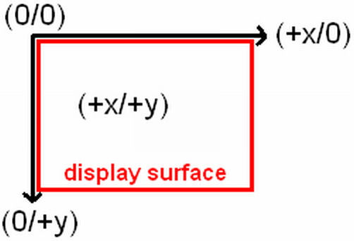
Now let’s have a look at the code. We define the rectangles called source_rect and destination_rect which store what part of the source image will be copied to what position at the destination surface (here: display surface). The command NEW(pointer) is a common Pascal command and should be known. source_rect and destination_rect are of type pSDL_RECT and are simple records which store a (x,y) and a (width, height) pair. The values set for both rectangles are identical. They are further exactly of the same size as our display surface and our image. The coordinates of x and y relate to the corresponding surface so (x/y) is (0/0) here for both rectangles and corresponds to the left upper corner. From this point to the right direction the width is 200 pixels. The height is from this point 200 pixels down to the bottom side of the display surface. The following image may explain this.
SDL_BLITSURFACE(src:pSDL_SURFACE; srcrect:pSDL_RECT; dst:pSDL_SURFACE; dstrect:pSDL_RECT):INTEGER is the needed command for blit processes. For successful blitting (copying) four parameters are requested. The first determines the source surface, the third the destination surface. The second and the fourth parameter can be NIL. Then the whole source surface is blitted to the (0,0) position (upper left corner) of the destination surface. If you want to blit the source surface to any other position on the destination surface (which is usually the case) you have to provide the coordinates by usage of the pSDL_RECT record. In the first run the content of surface “picture” within the defined rectangle of “source_rect” (x/y)=(0/0) and (w/h)=(200/200) is blitted to the display surface within the defined rectangle of “destination_rect” (x/y)=(0/0) and (w/h)=(200/200). Actually this means the complete content of the “picture” surface is blitted to the display surface.
After the blit process is finished the display surface has to be refreshed. Procedure SDL_UPDATERECT(screen:pSDL_SURFACE; x,y:SInt32; w,h:UInt32) or function SDL_FLIP(screen:pSDL_SURFACE):INTEGER are doing that. The SDL_FLIP(screen surface) command you use if you want to refresh the whole screen surface and furthermore if you want to use double buffering. For most applications and games therefore the SDL_FLIP(screen surface) is much more common. It is equal to SDL_UPDATERECT(screen surface,0,0,0,0) if double buffering is disabled. In comparision to SDL_UPDATERECT, SDL_FLIP furthermore returns an error value, 0 if successful and -1 on error.
The SDL_UPDATERECT command requests five parameters. The first parameter determines which surface has to be refreshed (usually the display surface). The next four ones determine a rectangel with: x-position, y-position (from top to bottom), width (relative to x,y-position), height (relative to x,y-position). If all of these paramters are “0” the whole surface will get updated.
In the example for any further cycle though the x, y, w and h values get incremented or decremented as shown. The destination-x and y values get incremented by one each cycle so it is progressing to the right bottom corner. This leads to the impression that the picture is slipping to the right bottom corner. The width and height values are fit respectivly.
The new introduced SDL_Delay(msec: UInt32) procedure works the same way as the common delay command of the CRT unit in Pascal. It delays the run of the program for the given time in milli seconds. This is a key procedure for nearly any program. If you would remove the delay procedure the program is running so fast, you wouldn’t be able to recognise the shifting but see some flickering. Since this sometimes even leads to abortions of the program I do not advise you to try it out.
ATTENTION: For a fast and clean blitting you should note that both surfaces (source and destination surface) should have the same bit depth! In our example we use a 32 bit screen surface (screen) and blit an 8 bit source surface (picture) onto it (because we loaded an 8 bit image file (fpsdl.bmp) to this surface). This is just an example and therefore it is okay, but you should avoid this especially if you plan to create games or applications where the FPS (frames per second) count is important.
IF source_rect^.w=1 THEN
  BEGIN
    source_rect^.x:=0;
    source_rect^.y:=0;
    source_rect^.w:=200;
    source_rect^.h:=200;
    destination_rect^.x:=0;
    destination_rect^.y:=0;
    destination_rect^.w:=200;
    destination_rect^.h:=200;
  END;
UNTIL keypressed;
The Repeat loop shrinkens the source rectangle from bottom right corner. At the same time the position at the destination surface is increased at the same rate. When the rectangles are of size 1 all values get restored.
The allocated memory of the picture and the display surface and of both rectangles get disposed. Finally SDL has to be quit and so has the program.
This file contains the source code: chap3.pas (right click and “save as”).
This file contains the executable: chap3.exe (right click and “save as”).
Hope you are successful and have fun. The final result should look and behave like this: The blue box with the text “Free Pascal meets SDL” is slipping to the right bottom corner. When it disappears the scene is reset.
 This image by https://www.freepascal-meets-sdl.net is licensed under a Creative Commons Attribution 4.0 International License.