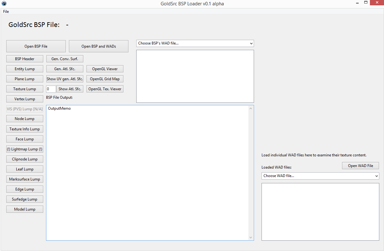
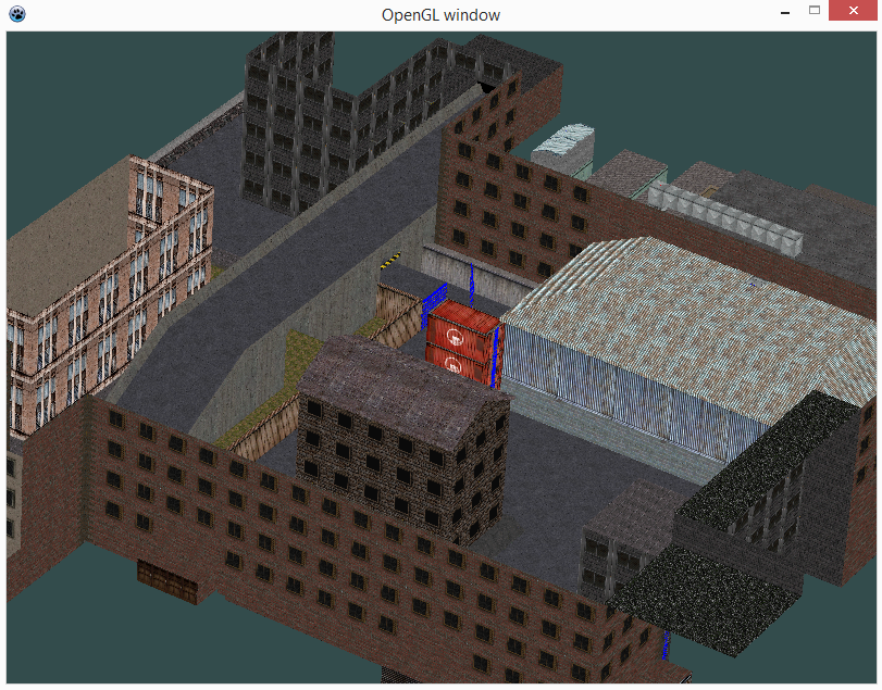
This project is a program to load GoldSrc BSP files. The GoldSrc BSP file format has been derived from the id’s Quake 2 file format by Valve Software for their Half-Life game series.
It has been realized with
Lazarus, Free Pascal
SDL2, OpenGL.
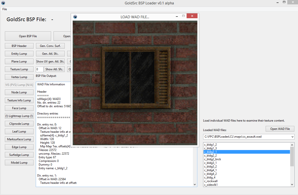
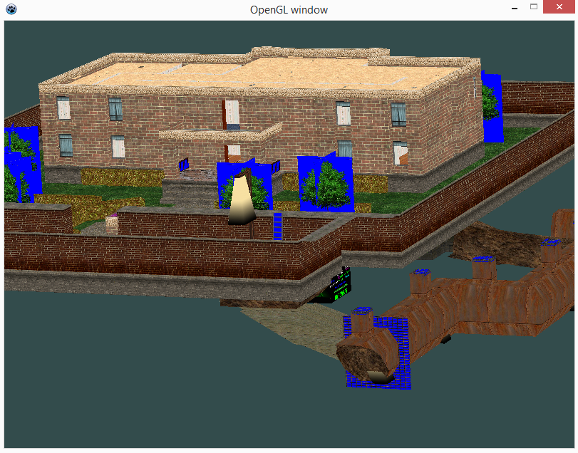
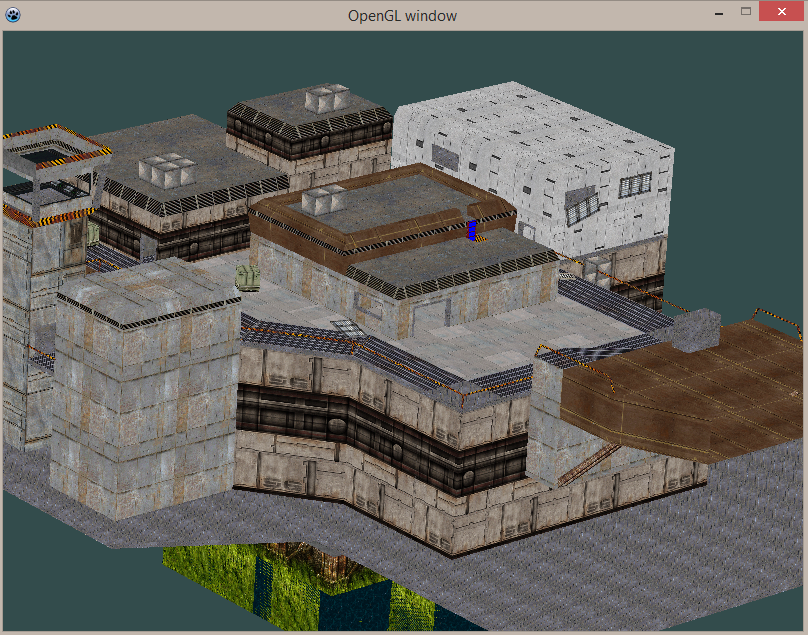
The BSP Loader powered by Lazarus.Loading a WAD file and displaying a selected texture from it.Textured rendering of a scene (estate). The blue colorkey is not interpreted to be transparent yet.Scene: Oilrig.Scene: Assault.
02/08/2018, v0.1 alpha
Capabilities
Load BSP files and show contents of data lumps (exception: VIS Lump)
Load WAD files and render contained textures
Load BSP file and all WAD files which are necessary to render the fully textured scene
Navigate by simple camera through scene
To-Do’s
lightmapping from lightmap data
VIS Lump: treat it at all
collision detection
face culling
have spaces between textures in atlas texture to prevent bleeding-effect (esp. in tiled textures recognizable)
make blue colorkey transparent
sky cube
release the source code (if beta stadium reached)
Important Sources
BSP and WAD File Formats
I cannot state how important these documents were in understanding the structure of the BSP and WAD file formats. Without them, this project wouldn’t have been possible.
Good news, Chapter 10 has been released right now! You ever wondered what to do if you would like to create 3d graphics for a game or application? – Well, you go for modern OpenGL. And SDL 2.0 is probably the best and most convenient way to go for modern OpenGL nowadays, even professionals typically use SDL as powerful assistant for their OpenGL applications. Learn more about the strong relationship between SDL and OpenGL in Chapter 10. – And learn how it’s done, of course ;-).
Chapter 3 got a short explanation now on how to copy the source code of a chapter. In the SDL 1.2 chapters the source code was shipped for each chapter as Pascal file. Nowadays it is much more convenient to grab the source code (or just the desired parts) by copying it directly from the chapter’s source code boxes (in the browser) and paste it whereever it is needed.
The transfer of the old website has been finished. Nearly the complete content is in some way or another transfered to the new page. For example, all tutorial pages (even the old ones) are still available. Some downloads are integrated at the corresponding tutorial pages now, so they are not lost. Some pages are gone, these are Downloads, Tables and Links. These pages are of no benefit anymore since their information are now provided at the corresponding place instead of separate pages. Nevertheless, links trying to access these pages are redirected to the main page to prevent broken links.
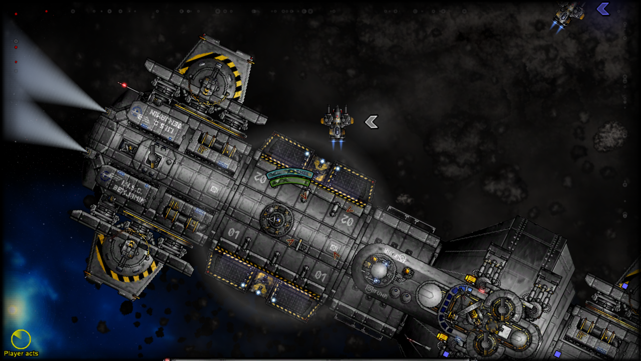
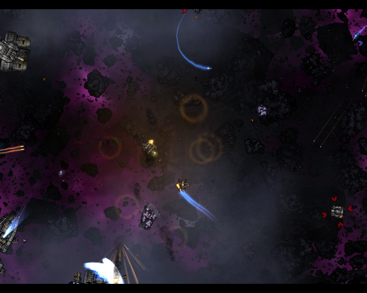
No One’s Space got greenlit. This means that this Free Pascal/SDL game will be available in Steam for purchase soon. It demonstrates the power of Free Pascal and SDL.
Small update of some subdomain settings. Subdomain links work again.
This chapter will introduce you on how to combine the SDL library with the famous Open Graphics Library (OpenGL).
What is OpenGL?
OpenGL is the first choice when it comes to platform independent 2d and 3d graphics programming. The emphasis is on graphics programming only though!
Why and when to combine SDL and OpenGL?
SDL is an excellent choice if you need platform independent 2d graphics. OpenGL is capable of 2d graphics, too, but why using the more complicated library if you could use the easy to use SDL library? – And by the way, underneath SDL is actually using OpenGL (or similar libraries depending upon the system) to achieve its hardware accelerated 2d graphics.
However, if your project needs 3d graphics, which isn’t covered by SDL, you can set up your system for this quite easy with SDL. The setup of an OpenGL environment is very easy and platform independent with SDL. Without SDL you would’ve to write different code to set up OpenGL for each operating system. In fact, even professional developers use SDL to set up their OpenGL applications.
Furthermore, since OpenGL is a pure graphics library, any other task is further done by SDL (e.g. keyboard handling, sound,…).
At this point I’d like to quote Klaus Vor der Landwehr (professional developer) from Turtle-Games, who described the relation of SDL and OpenGL in a very clear way.
Although the graphics are often in the foreground, it is for me as a game programmer only one aspect of many with which I have to deal. And the graphics do not even require the most work. OpenAL for example costs much more time and effort if you want to build a 3D sound channel management. And there are many other interfaces. Here is a list of categories in which SDL has been a great help:
As of version 2.0 of OpenGL, the so-called fixed pipeline has been replaced by a programmable pipeline (modern OpenGL). In general, the pipeline makes your input data appear on the screen in a hardware accelerated manner by using your graphics card. For the fixed pipeline it was easy to draw something to the screen but, as the name suggests, it was quite fixed and unflexible. The programmable pipeline which is controlled by a newly introduced shader (script) language is far more flexible, though, the ease is gone :-D.
Anyway, some people refer to OpenGL version 3.0 and up as modern OpenGL. This is because a lot of typical functionality was deprecated as of this version. The backwards compatibility is gone.
In this chapter I will demonstrate how to use SDL 3.0 and up to set up a modern OpenGL environment using some basic shaders. I based the description heavily on an excellent C++ tutorial over at opengl-tutorial.org and their second chapter. You may look for further OpenGL stuff there or have a look at this WikiBook OpenGL Introduction (C++). I’m not aware of OpenGL tutorials for Free Pascal or Delphi treating modern OpenGL (let me know if you know).
OpenGL Pascal units (headers)
Similar to SDL 2.0, you need specific units which translate and connect your code to the OpenGL library. There is a native OpenGL unit GL which covers the main functionality of OpenGL. Additionally for modern OpenGL you need the unit GLext which covers the functionality up to OpenGL version 4.0. These units are shipped right along with the Free Pascal compiler.
In case you are interested in support of OpenGL version 4.4, you should look into the dglOpenGL.pas. This unit is not shipped natively along with the Free Pascal compiler.
Let the fun begin
Let’s have a look at the code:
program chap10_SDL2;
uses Classes, SysUtils, SDL2, GL, GLext;

const
  vertexShaderFile = 'VertexShader.txt';
  fragmentShaderFile = 'FragmentShader.txt';
  triangleData: array[0..8] of GLfloat = ( -1.0, -1.0, 0.0,
                                            1.0, -1.0, 0.0,
                                            0.0,  1.0, 0.0  );

var
sdlWindow1: PSDL_Window;
sdlGLContext1: TSDL_GLContext;
i: Word;
VertexArrayID: GLuint;
triangleVBO: GLuint;

VertexShaderID: GLuint;
VertexShaderCode: PGLchar;
FragmentShaderID: GLuint;
FragmentShaderCode: PGLchar;
ShaderCode: TStringList;
ProgramID: GLuint;
compilationResult: GLint = GL_FALSE;
InfoLogLength: GLint;
ErrorMessageArray: array of GLChar;

begin
  if SDL_Init( SDL_INIT_VIDEO ) < 0 then HALT;

  //get an OpenGL window and create OpenGL context
  sdlWindow1 := SDL_CreateWindow( 'OpenGL window', 50, 50, 500, 500, SDL_WINDOW_OPENGL );
  if sdlWindow1 = nil then HALT;

  sdlGLContext1 := SDL_GL_CreateContext( sdlWindow1 );
  if @sdlGLContext1 = nil then HALT;

  //init OpenGL and load extensions
  if Load_GL_VERSION_4_0 = false then
    if Load_GL_VERSION_3_3 = false then
      if Load_GL_VERSION_3_2 = false then
        if Load_GL_VERSION_3_0 = false then
        begin
          writeln(' ERROR: OpenGL 3.0 or higher needed. '); readln;
          HALT;
        end;

  //print out OpenGL vendor, version and shader version
  writeln( 'Vendor: ' + glGetString( GL_VENDOR ) );
  writeln( 'OpenGL Version: ' + glGetString( GL_VERSION ) );
  writeln( 'Shader Version: ' + glGetString( GL_SHADING_LANGUAGE_VERSION ) );

  //create Vertex Array Object (VAO)
  glGenVertexArrays( 1, @VertexArrayID );
  glBindVertexArray( VertexArrayID );

  //creating Vertex Buffer Object (VBO)
  glGenBuffers( 1, @triangleVBO );
  glBindBuffer( GL_ARRAY_BUFFER, triangleVBO );
  glBufferData( GL_ARRAY_BUFFER, SizeOf( triangleData ), @triangleData, GL_STATIC_DRAW );

  //creating shaders
  VertexShaderID := glCreateShader( GL_VERTEX_SHADER );
  FragmentShaderID := glCreateShader( GL_FRAGMENT_SHADER );

  //load shader code and get PChars
  ShaderCode := TStringList.Create;
  ShaderCode.LoadFromFile( VertexShaderFile );
  VertexShaderCode := ShaderCode.GetText;
  if VertexShaderCode = nil then HALT;
  ShaderCode.LoadFromFile( FragmentShaderFile );
  FragmentShaderCode := ShaderCode.GetText;
  if FragmentShaderCode = nil then HALT;
  ShaderCode.Free;

  //compiling and error checking vertex shader
  write('Compiling and error checking Vertex Shader... ' );
  glShaderSource( VertexShaderID, 1, @VertexShaderCode, nil );
  glCompileShader( VertexShaderID );

  glGetShaderiv( VertexShaderID, GL_COMPILE_STATUS, @compilationResult );
  glGetShaderiv( VertexShaderID, GL_INFO_LOG_LENGTH, @InfoLogLength );
  if compilationResult = GL_FALSE then
  begin
    writeln( 'failure' );
    SetLength( ErrorMessageArray, InfoLogLength+1 );
    glGetShaderInfoLog( VertexShaderID, InfoLogLength, nil, @ErrorMessageArray[0] );
    for i := 0 to InfoLogLength do write( String( ErrorMessageArray[i] ) );
    writeln;
  end else writeln( 'success' );

  //compiling and error checking fragment shader
  write('Compiling and error checking Fragment Shader... ' );
  glShaderSource( FragmentShaderID, 1, @FragmentShaderCode, nil );
  glCompileShader( FragmentShaderID );

  glGetShaderiv( FragmentShaderID, GL_COMPILE_STATUS, @compilationResult );
  glGetShaderiv( FragmentShaderID, GL_INFO_LOG_LENGTH, @InfoLogLength );
  if compilationResult = GL_FALSE then
  begin
    writeln( 'failure' );
    SetLength( ErrorMessageArray, InfoLogLength+1 );
    glGetShaderInfoLog( VertexShaderID, InfoLogLength, nil, @ErrorMessageArray[0] );
    for i := 0 to InfoLogLength do write( String( ErrorMessageArray[i] ) );
    writeln;
  end else writeln( 'success' );

  //creating and linking program
  write('Creating and linking program... ' );
  ProgramID := glCreateProgram();
  glAttachShader( ProgramID, VertexShaderID );
  glAttachShader( ProgramID, FragmentShaderID );
  glLinkProgram( ProgramID );

  glGetShaderiv( ProgramID, GL_LINK_STATUS, @compilationResult );
  glGetShaderiv( ProgramID, GL_INFO_LOG_LENGTH, @InfoLogLength );
  if compilationResult = GL_FALSE then
  begin
    writeln( 'failure' );
    SetLength( ErrorMessageArray, InfoLogLength+1 );
    glGetShaderInfoLog( VertexShaderID, InfoLogLength, nil, @ErrorMessageArray[0] );
    for i := 0 to InfoLogLength do write( String( ErrorMessageArray[i] ) );
    writeln;
  end else writeln( 'success' );

  for i := 0 to 400 do
  begin
    glClearColor( 0.0, 1.0-i/400, 0.0+i/400, 1.0 );
    glClear( GL_COLOR_BUFFER_BIT );
    glUseProgram( ProgramID );
    glEnableVertexAttribArray( 0 );
    glBindBuffer( GL_ARRAY_BUFFER, triangleVBO );
    glVertexAttribPointer( 0, 3, GL_FLOAT, GL_FALSE, 0, nil );
    glDrawArrays( GL_TRIANGLES, 0, 3 );
    glDisableVertexAttribArray( 0 );
    SDL_Delay( 20 );
    SDL_GL_SwapWindow( sdlWindow1 );
  end;

  //clean up
  glDetachShader( ProgramID, VertexShaderID );
  glDetachShader( ProgramID, FragmentShaderID );

  glDeleteShader( VertexShaderID );
  glDeleteShader( FragmentShaderID );
  glDeleteProgram( ProgramID );

  StrDispose( VertexShaderCode );
  StrDispose( FragmentShaderCode );

  glDeleteBuffers( 1, @triangleVBO );
  glDeleteVertexArrays( 1, @VertexArrayID );

  SDL_GL_DeleteContext( sdlGLContext1 );
  SDL_DestroyWindow( sdlWindow1 );

  SDL_Quit;
end.
Wow that is a lot of code. What you will get is this:
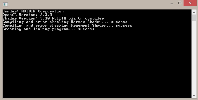
The background will change slowly from green to blue. And you will get this:
The vendor, OpenGL version and shader version information will be different according to your system. Also, if your system doen’t support the needed OpenGL version you’ll not have “success” but rather “failure” after the compiling and linking processes. Additional information may be shown then.
The program is called “chap10_SDL2” for obvious reason.
Additionally to the SDL2 unit we load the native FPC units Classes (for TStringList support), SysUtils (for PChar functions) and GL and GLext for OpenGL support.
Thre are three constants declared. The first two are defined as the filenames of the so-called shader source files. Basically they are simple text files which contain a script. More about shaders and the script later. The third is an array of nine GLfloat values. GLfloat is the OpenGL float variable type which in fact is translated as Pascal’s Single type. In short, these nine values describe three points in 3d space which, if connected, form a triangle. More about this later.
The first variable “sdlWindow1” is well known from previous chapters. Any variable to follow is new though. Most of them are related to OpenGL.
“sdlGLContext1” is of type TSDL_GLContext needed to create a so-called OpenGL context. In fact, this variable type is provided by SDL and a key type to set up an OpenGL conext in a simple and cross-platform manner.
The variable “i” is a simple Word variable for counting purposes.
OpenGL’s Integers and Strings
Most of the following variables are either of type GLuint or of type PGLchar. The last variable is an dynamic array of GLchars. Their specific meaning will be discussed later but GLuint is the OpenGL unsigned integer type (no negative values) which translates to Pascal’s Cardinal/Longword type. Text handling in OpenGL works by null-terminated strings of type PGLchar which translate to Pascal’s PChar. GLchar translates to Char then, obviously.
At this point you may wonder why as for SDL the null-terminated strings are used instead of simple strings (see Chapter 7 for the PAnsiChar variable type discussion). The answer again is that OpenGL is based upon C which handles strings this way. PChar equals PAnsiChar by the way.
The remaining variables “ShaderCode” of type TStringList will be used to handle the shader text files. “compilationResult” and “InfoLogLength” are of GLint type. In contrast to GLuint they allow for negative values.
begin
  if SDL_Init( SDL_INIT_VIDEO ) < 0 then HALT;

  //get an OpenGL window and create OpenGL context
  sdlWindow1 := SDL_CreateWindow( 'OpenGL window', 50, 50, 500, 500, SDL_WINDOW_OPENGL );
  if sdlWindow1 = nil then HALT;

  sdlGLContext1 := SDL_GL_CreateContext( sdlWindow1 );
  if @sdlGLContext1 = nil then HALT;

  //init OpenGL and load extensions
  if Load_GL_VERSION_4_0 = false then
    if Load_GL_VERSION_3_3 = false then
      if Load_GL_VERSION_3_2 = false then
        if Load_GL_VERSION_3_0 = false then
        begin
          writeln(' ERROR: OpenGL 3.0 or higher needed. '); readln;
          HALT;
        end;

  //print out OpenGL vendor, version and shader version
  writeln( 'Vendor: ' + glGetString( GL_VENDOR ) );
  writeln( 'OpenGL Version: ' + glGetString( GL_VERSION ) );
  writeln( 'Shader Version: ' + glGetString( GL_SHADING_LANGUAGE_VERSION ) );
First SDL2 is initilized as known. “sdlWindow1” is created as known by SDL_CreateWindow. Be careful though, in order to work with OpenGL the flag SDL_WINDOW_OPENGL has to be set!
SDL 2.0 and the OpenGL context
An OpenGL context is kind of an abstract name. It doesn’t represents just a window, even though it is created from a SDL2 window, but rather it contains everything (including the window information) that is related to this OpenGL context. The OpenGL context is therefore kind of “broader” than just a window, that is why it is called context rather than just a OpenGL window.
The function to create an OpenGL context from a SDL2 window is:
function SDL_GL_CreateContext(window: PSDL_Window): TSDL_GLContext
So, it is simple as that, just use the SDL2 window as argument and voila, you’ll get a OpenGL context, platform-independent. That is why everybody loves SDL2 to work with OpenGL. Note that the returned Context isn’t a pointer but an actual instance. So to error check against nil you need to refer to the instance’s addresse by the @ operator.
OpenGL version check and initialization
The nested if-then-statements check if at least version 3.0 of OpenGL is installed. If so, the highest available version is loaded. If not, the program is stopped and returns a text message.
If your hardware doen’t support OpenGL 3.0 or higher you should try to update your graphics driver. There is a good chance that you are able to use OpenGL 3.0 or higher then. Anyway, if the upgrade doesn’t work out or you wouldn’t want to update, you may have a look into the JEDI-SDL Chapter about OpenGL, there the old OpenGL is treated (although that chapter treats SDL 1.2, it shouldn’t be too hard to make it work with SDL 2.0 with minor changes).
Next there are three text messages printed out. These present the Vendor, the OpenGL version and the Shading language version. To get them in a readable form you need to transform the constants into strings by function glGetString. Let’s have a look at the command window again:
Have a look at the first three lines and you see what it could look like.
If you are new to OpenGL, OpenGL as kind of machine with many switches. Each switch
Briefly, a Vertex Array Object (VAO) is a specific OpenGL object which contains important settings (e.g. format of vertex data) and references to other objects, including Vertex Buffer Objects (VBO). Notice, it doesn’t store the object’s data (content) itself, it just stores the reference to these objects.
The Vertex Buffer Object (VBO) contains the actual data (content). In the example case these are three vertices, each described by three float point values in cartesian space.
OpenGL Object name or ID
Because it is important to understand, in contrast to SDL where objects usually are directly submitted to a function by its pointer reference, in OpenGL you have a so-called OpenGL Object name, which actually is an integer value of GLuint type. Therefore ID is a suitable name, too. Let’s see how this works:
The VAO is created by function glGenVertexArrays( number of VAO names, pointer to VAO names array ). The first parameter determines how many VAO names I’d like to create. We just need 1. The second parameter asks for a pointer to an array of VAO names. Since VAO names are just simple GLuints, it is a simple array of GLuints. Anyway, since we just need one, a pointer to a simple GLuint variable will be suitable, too. In our case that is “VertexArrayID”. To bind (“activate”) the corresponding VAO to the OpenGL context, the function glBindVertexArray( name of VAO ) is used. The argument is the name of the VAO we just created in “VertexArrayID”.
Similar to the VAO, the VBO is created by function glGenBuffers( number of VBO names, pointer to VBO names array ). Again, we just need 1 VBO whose name should be returned to “triangleVBO”. This variable just stores an ID (object name) of GLuint type.
From the naming of “triangleVBO” it is clear to us what we intent here (representing a triangle by three vertices), anyway, how should OpenGL know? – We explain the meaning of this buffer object to OpenGL by using glBindBuffer ( target, VBO name ). There are numerous options as target but GL_VERTEX_BUFFER is the right choice here.
The actual VBO is created by glBufferData( target, size of object’s data store in bytes, pointer to data to be copied into VBO, expected usage ). This functions takes four arguments. The target is GL_VERTEX_BUFFER again. The size of the VBO’s data store in bytes is determined by Pascal’s SizeOf function applied to “triangleData”. The “triangleData” constant also holds the data to be copied into the VBO, so its pointer is suitable as the third argument. Since we are not going to change the data a lot, we should use GL_STATIC_DRAW as fourth argument.
If you are a newcomer to OpenGL, don’t worry if you are confused the first time. Most people are. And now it may even get worse :-(.
Shaders and OpenGL Shading Language
When starting with modern OpenGL the so-called Shaders are talked about a lot. Shaders are scripts written in a C-like script language called OpenGL Shading Language (GLSL). These scripts are compiled at runtime and influence the way how the graphics data is processed at certain steps in the so-called rendering pipeline of OpenGL. In fact, you can create rather complex and special effects with shaders without even changing one line of code of your source code.
Vertex Shader and Fragment Shader
There are two Shaders that are crucial and have to be set up to work with modern OpenGL. They are called Vertex Shader and Fragment Shader. There are more Shaders not covered here, though. Each type of Shader influences different aspects of the rendering.
The Vertex Shader is the first Shader program executed in the rendering pipeline. Every vertex is “put through” the Vertex Shader program and processed accordingly, hence the name. Often this Shader is used to perform transformation operations. The Shader script used in this tutorial is shown next:
This GLSL source code is saved into a file VertexShader.txt and located in the same directory as the source code of this chapter’s example source code. I’m not going to explain this GLSL code in detail here, but a detailed explanation is found over at opengl-tutorial.org Chapter 2 where I got this Shader code from, by the way.
The Frgament Shader is the last Shader program executed in the renderin pipeline. The so-called rasterization process produces fragments. Every fragment is “put through” the Fragment Shader program and processed accordingly. The Shader script used for the Fragment Shader is:
#version 330 core

out vec3 color;

void main(){
   color = vec3(1,0,0);
 }
This code is in file FragmentShader.txt and located in the same directory as the VertexShader.txt. The detailed explanation is found over at opengl-tutorial.org Chapter 2 again. Anyway, you’ll notice that there is a “color” variable (three component vector). As you see, it sets the (red,green,blue) values for the fragments to (1,0,0) which means red should be the result, red = 100%, green and blue = 0%. You may play around with these values.
  //creating shaders
  VertexShaderID := glCreateShader( GL_VERTEX_SHADER );
  FragmentShaderID := glCreateShader( GL_FRAGMENT_SHADER );

  //load shader code and get PChars
  ShaderCode := TStringList.Create;
  ShaderCode.LoadFromFile( VertexShaderFile );
  VertexShaderCode := ShaderCode.GetText;
  if VertexShaderCode = nil then HALT;
  ShaderCode.LoadFromFile( FragmentShaderFile );
  FragmentShaderCode := ShaderCode.GetText;
  if FragmentShaderCode = nil then HALT;
  ShaderCode.Free;
Both Shaders are created by function glCreateShader( Shader type ). It returns the reference (or name) as GLuint as seen before for the VAO and VBO. We store them in the VertexShaderID and FragmenShaderID, respecitvely.
The next part is about loading the source code from the two Shader files (VertexShader.txt, FragmentShader.txt) and converting them to be used with OpenGL. First a “ShaderCode” variable of TStringList type is created. Its LoadFromFile method let us load the file contents into the variable conveniently. First for the Vertex Shader, whose file name is stored in constant “VertexShaderFile”. The variable “VertexShaderCode” is of type PGLchar, which is the way OpenGL handles strings. Since PGLchar is of type PChar anyway, the method GetText is perfectly suitable here to convert the source code string into a null-terminated array of chars. Finally, there is a simple check if the PGLchars are empty (nil), which shouldn’t be the case if the source code is pointed to as expected.
Exactly the same is done for the FragmentShader and the source code associated with “FragmentShaderCode”.
Finally, the dummy variable “ShaderCode” is free’d.
  //compiling and error checking vertex shader
  write('Compiling and error checking Vertex Shader... ' );
  glShaderSource( VertexShaderID, 1, @VertexShaderCode, nil );
  glCompileShader( VertexShaderID );

  glGetShaderiv( VertexShaderID, GL_COMPILE_STATUS, @compilationResult );
  glGetShaderiv( VertexShaderID, GL_INFO_LOG_LENGTH, @InfoLogLength );
  if compilationResult = GL_FALSE then
  begin
    writeln( 'failure' );
    SetLength( ErrorMessageArray, InfoLogLength+1 );
    glGetShaderInfoLog( VertexShaderID, InfoLogLength, nil, @ErrorMessageArray[0] );
    for i := 0 to InfoLogLength do write( String( ErrorMessageArray[i] ) );
    writeln;
  end else writeln( 'success' );

  //compiling and error checking fragment shader
  write('Compiling and error checking Fragment Shader... ' );
  glShaderSource( FragmentShaderID, 1, @FragmentShaderCode, nil );
  glCompileShader( FragmentShaderID );

  glGetShaderiv( FragmentShaderID, GL_COMPILE_STATUS, @compilationResult );
  glGetShaderiv( FragmentShaderID, GL_INFO_LOG_LENGTH, @InfoLogLength );
  if compilationResult = GL_FALSE then
  begin
    writeln( 'failure' );
    SetLength( ErrorMessageArray, InfoLogLength+1 );
    glGetShaderInfoLog( VertexShaderID, InfoLogLength, nil, @ErrorMessageArray[0] );
    for i := 0 to InfoLogLength do write( String( ErrorMessageArray[i] ) );
    writeln;
  end else writeln( 'success' );
To associate the source code we stored in “VertexSourceCode” to “VertexShaderID” of GLuint type, the function glShaderSource( Shader reference, number of array elements, pointer to array of source code PGLchars, pointer to array of lengths ). The Vertex Shader reference is stored in “VertexShaderID” which is the first argument. We just have one source code, so the second argument is 1. The source code is stored VertexShaderCode, and its pointer is addressed by @VertexShaderCode as the third argument. As seen before, since we just have one element here, it is not necessary to have really an array. The fourth parameter allows for some length specification, but if set to nil it expects null-terminated arrays of chars.
The compilation is straight forward done by glCompileShader( Shader reference ). It is really advised to to error checking here, that is why it is shown how to do that. The function glGetShaderiv( Shader reference, object parameter, pointer of correct type for return value ) is used to request information about objects. First we like to know if the compilation was successful. The Shader reference is stored in “VertexShaderID”, the object parameter is GL_COMPILE_STATUS. This will return a GLint value, which can be interpreted as GL_FALSE or GL_TRUE. The result is stored in “compilationResult” by using its pointer (@compilationResult) as argument.
Right after that we request the length of the information log by GL_INFO_LOG_LENGTH. It will be greater than 0 if some information were logged (probably an error occured on compilation then). The result is returned to “InfoLogLength” by its pointer @InfoLogLength.
If an error occurs, “compilationResult” is GL_FALSE. In this case “failure” along with more specific information is printed out. I’m not going into detail here, since this shouldn’t happen. Otherwise (and that should be the case), “success” is printed out.
The very same way the Fragment Shader is compiled and checked.
  //creating and linking program
  write('Creating and linking program... ' );
  ProgramID := glCreateProgram();
  glAttachShader( ProgramID, VertexShaderID );
  glAttachShader( ProgramID, FragmentShaderID );
  glLinkProgram( ProgramID );

  glGetShaderiv( ProgramID, GL_LINK_STATUS, @compilationResult );
  glGetShaderiv( ProgramID, GL_INFO_LOG_LENGTH, @InfoLogLength );
  if compilationResult = GL_FALSE then
  begin
    writeln( 'failure' );
    SetLength( ErrorMessageArray, InfoLogLength+1 );
    glGetShaderInfoLog( VertexShaderID, InfoLogLength, nil, @ErrorMessageArray[0] );
    for i := 0 to InfoLogLength do write( String( ErrorMessageArray[i] ) );
    writeln;
  end else writeln( 'success' );
The shaders have to be attached and linked by a Shader program. A Shader program is created by glCreateProgram(). The parenthesis are important here. It returns an reference of GLuint type which is stored in ProgramID.
The Shaders are attached to this Shader program by glAttacheShader( Program reference, Shader reference ). The program is linked by glLinkProgram( Program reference ). The reference for the Shader program is “ProgramID”. The references for the Shaders are “VertexShaderID” and “FragmentShaderID”, respectively.
By complete analogy to the error checking for the Shader compilation, the Shader program linking is checked. Anyway, instead of GL_COMPILE_STATUS, GL_LINK_STATUS is used.
  for i := 0 to 400 do
  begin
    glClearColor( 0.0, 1.0-i/400, 0.0+i/400, 1.0 );
    glClear( GL_COLOR_BUFFER_BIT );
    glUseProgram( ProgramID );
    glEnableVertexAttribArray( 0 );
    glBindBuffer( GL_ARRAY_BUFFER, triangleVBO );
    glVertexAttribPointer( 0, 3, GL_FLOAT, GL_FALSE, 0, nil );
    glDrawArrays( GL_TRIANGLES, 0, 3 );
    glDisableVertexAttribArray( 0 );
    SDL_Delay( 20 );
    SDL_GL_SwapWindow( sdlWindow1 );
  end;
The for-loop counts from 0 to 400. Within each cycle it first changes the background color by glClearColor( red, green, blue, alpha ). Red and alpha are constant, green and blue are varied each cycle dependend upon variable i. This makes the background slowly changing from green to blue, feel free to play around with the rgba values. To actually clear the color buffer glClear( buffer ) with GL_COLOR_BUFFER_BIT as argument is used.
glUseProgram( Shader program reference ) is used to apply the Shader program to the rendering state. “ProgramID” is the Shader program reference in the example code.
glEnableVertexAttribArray( array index ) is used in order to make the attribute array available for rendering by glDrawArrays. The index is 0 here. The “triangleVBO” is bound by glBindBuffer( target, buffer ) to the GL_BUFFER_ARRAY target to change attribute data of said VBO. Latter is done by glVertexAttribPointer( index, size, type, normalized, stride, offset of first component ) with the given arguments. Hence, the index is 0, 3 components per generic vertex attribute, each of float point type (thus, GL_FLOAT), not normalized (thus GL_FALSE), no strides between vertex attributes, no offset for the first component.
The rendering is done by glDrawArrays( type of primitive, starting index, number of elements ). The type of primitive is a triangle, hence GL_TRIANGLES is the first argument. We start at the very beginning, so index is 0. We have 3 sequential elements (vertices).
glDisableVertexAttribArray( array index ) is the counter function to glEnableVertexAttribArray( array index ), obviously. It disables the vertex attribute array.
SDL_Delay delays the loop by 20 milliseconds.
The procedure
procedure SDL_GL_SwapWindow(window: PSDL_Window)
is used to actually display the rendering result to the the window “sdlWindow1”. Keep in mind that this window has to be initialized as an OpenGL window. This procedure is comparable to SDL’s SDL_RenderPresent.
For the clean up, the shaders have to be detached from the shader program by glDetachShader( program, shader ). After that they can be deleted by glDeleteShader( shader ), and the program by glDeleteProgram( program ).
The shader script PChars are disposed by StrDispose( PChar ).
The VBO and the vertex array have to be free’d by glDeleteBuffers( number of buffer objects, pointer to array of buffers ) and glDeleteVertexArrays( number of VAOs, pointer to array of VAOs ) respectively. The first parameter is the number of objects to be deleted, which is 1 in both our cases.
Interview with Klaus Vor der Landwehr from Turtle-Games
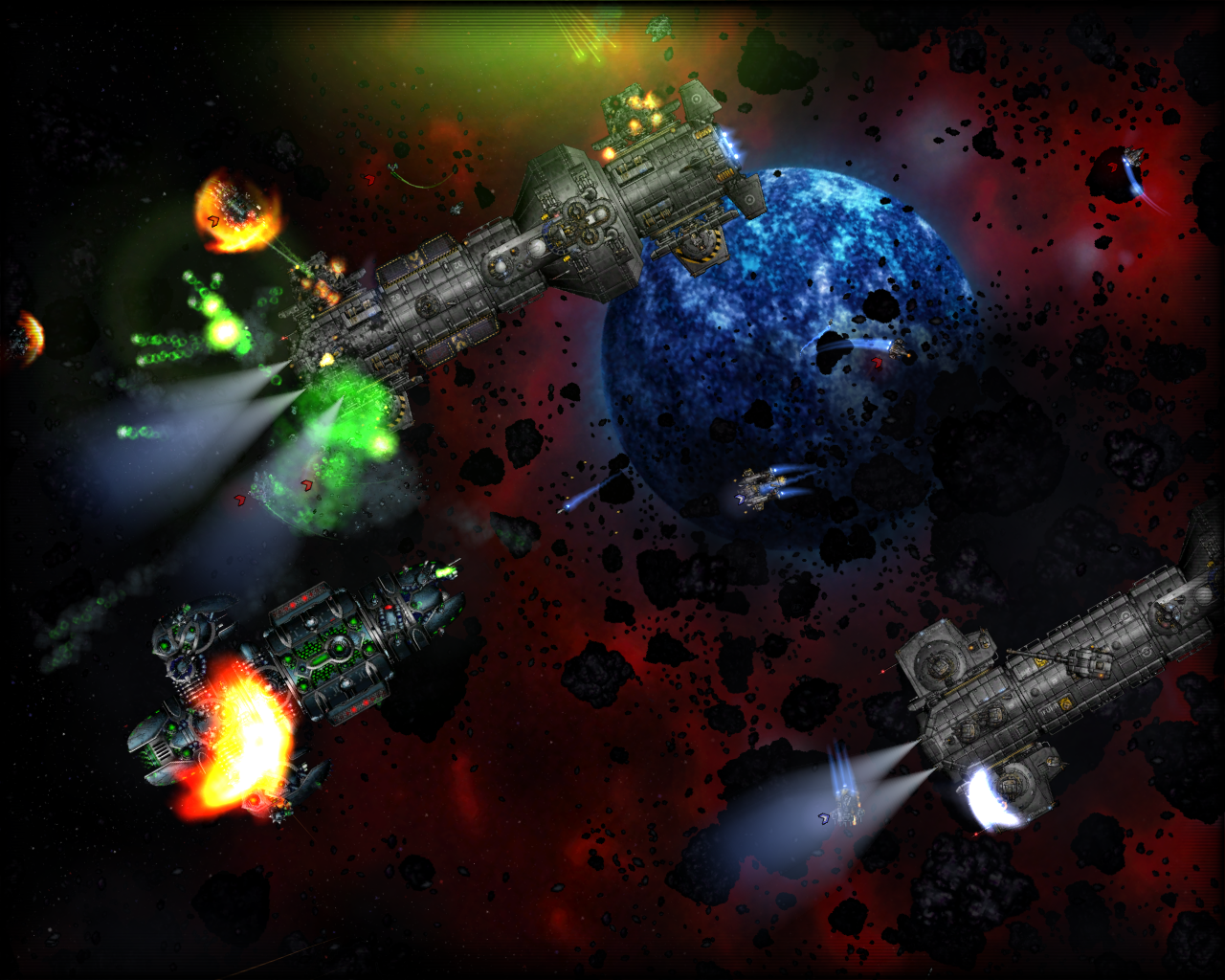
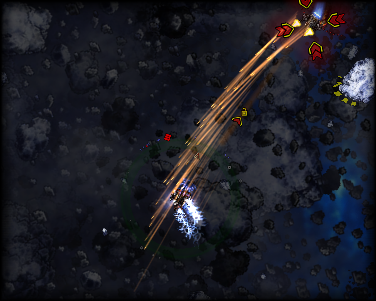
Could you please give a short description of No One’s Space for those who have never heard of it?
Klaus Vor der Landwehr: No One’s Space (NOS) is a single-player Retro 2D-Science-Fiction-Shooter with modern physics. It was created as a cross-breed of the classic games Wing Commander I and Star Control II. In NOS, the player experiences a cosmic conflict between four powerful races, taking the role of different heroes. In 54 challenging missions, reaching from manageable duels to large combats, the player controls a variety of vessels and has to go all out to improve his skills to master them all.
Why did you decide to choose Pascal as a programming language and SDL/SDL2 as a library for this project?
Klaus Vor der Landwehr: It wasn’t really a choice. I’m used to Pascal since my school days. I’m a self-taught. I like it.
What do you think is the most interesting Pascal/SDL/SDL2 project out there (besides your own, of course :-D)?
Klaus Vor der Landwehr: Hm, as far as it concerns the programming language, games are rarely tagged. But I’ve seen some impressive stuff right here: Projekt “W” – Phase 2 http://www.saschawillems.de/?page_id=829 (Although I can only assume that it uses SDL).
Are there any further steps for No One’s Space and/or are any new projects planned? What will they be?
Klaus Vor der Landwehr: If the game gets Greenlit, we want to release it on Steam this year (early access) and work further on it.
This is an SDL 1.2 chapter. SDL 1.2 is obsolete since it has been replaced by SDL 2.0. Unless you have good reasons to stay here you may prefer to go for the modern SDL 2.0 :-).
It is highly recommended that you read the previous Chapter 8. The code from last chapter was used and modified to show how the conversion works. However, I won’t explain twice everything already introduced in Chapter 8. Also I’d like to express here that NeHe Productions’ OpenGL tutorial 06 “Texture Mapping” and the translated (by Dominique Louis) Jedi-SDL file was inspiring me a lot for this chapter.
You need this software:
Software
Version
Source
Description
OpenGL driver
–
–
Usually your graphic card provides the corresponding OpenGL driver and you don’t have to do anything. And if so it is very likely that version 1.1 is fully supported. However if you are one of the few poor people whose graphic card doesn’t support OpenGL, check the graphic card’s manufacturer’s homepage for OpenGL drivers.
Now following the whole code at once as usual. As you will notice many lines are exactly the same as in Chapter 8.
PROGRAM chap8a;
USES CRT, SDL, GL, GLU;

VAR
userkey:CHAR;
screen, picture:pSDL_SURFACE;
h,hh,th,thh:REAL;
ogl_texture:pGLUINT;

BEGIN

//some calculations needed for a regular tetrahedron with side length of 1
h:=SQRT(0.75); //height of equilateral triangle
hh:=h/2;       //half height of equilateral triangle
th:=0.75;      //height of tetrahedron
thh:=th/2;     //half height of tetrahedron

SDL_INIT(SDL_INIT_VIDEO);

SDL_GL_SETATTRIBUTE(SDL_GL_RED_SIZE, 5);
SDL_GL_SETATTRIBUTE(SDL_GL_GREEN_SIZE, 5);
SDL_GL_SETATTRIBUTE(SDL_GL_BLUE_SIZE, 5);
SDL_GL_SETATTRIBUTE(SDL_GL_DEPTH_SIZE, 16);
SDL_GL_SETATTRIBUTE(SDL_GL_DOUBLEBUFFER, 1);

screen:=SDL_SETVIDEOMODE(640, 480, 0, SDL_OPENGL);
IF screen=NIL THEN HALT;

//preparing SDL image
picture:=SDL_LOADBMP('C:\fpsdl256.bmp');
IF picture=NIL THEN HALT;

//preparing OpenGL texture
NEW(ogl_texture);
glGENTEXTURES(1, ogl_texture);
glBINDTEXTURE(GL_TEXTURE_2D, ogl_texture^);
glTEXIMAGE2D(GL_TEXTURE_2D, 0, 3, picture^.w, picture^.h, 0,
             GL_RGB, GL_UNSIGNED_BYTE, picture^.pixels);
glTEXPARAMETERi(GL_TEXTURE_2D, GL_TEXTURE_MIN_FILTER, GL_LINEAR);
glTEXPARAMETERi(GL_TEXTURE_2D, GL_TEXTURE_MAG_FILTER, GL_LINEAR);
SDL_FREESURFACE(picture);


glCLEARCOLOR(0.0, 0.0, 1.0, 0.0);
glVIEWPORT(0,0,640,480);
glMATRIXMODE(GL_PROJECTION);
glLOADIDENTITY;
gluPERSPECTIVE(45.0, 640.0/480.0, 1.0, 3.0);
glMATRIXMODE(GL_MODELVIEW);
glLOADIDENTITY;
glCLEAR(GL_COLOR_BUFFER_BIT);
glENABLE(GL_CULL_FACE);
glTRANSLATEf(0.0, 0.0, -2.0);

REPEAT
SDL_DELAY(50);

glROTATEf(5, 0.0, 1.0, 0.0);
glCLEAR(GL_COLOR_BUFFER_BIT);

//drawing textured face of tetrahedron
glENABLE(GL_TEXTURE_2D);
glBEGIN(GL_TRIANGLES);
    glTEXCOORD2f(2,2);
    glVERTEX3f(thh, 0.0, 0.0);
    glTEXCOORD2f(0,0);
    glVERTEX3f(-thh, hh, 0.0);
    glTEXCOORD2f(0,2);
    glVERTEX3f(-thh, -hh, 0.5);
glEND;
glDISABLE(GL_TEXTURE_2D);

//drawing remaining three untextured faces
glBEGIN(GL_TRIANGLES);
    glCOLOR3f(0.0, 1.0, 1.0);
    glVERTEX3f(thh, 0.0, 0.0);
    glVERTEX3f(-thh, -hh, -0.5);
    glVERTEX3f(-thh, hh, 0.0);

    glCOLOR3f(1.0, 0.0, 1.0);
    glVERTEX3f(thh, 0.0, 0.0);
    glVERTEX3f(-thh, -hh, 0.5);
    glVERTEX3f(-thh, -hh, -0.5);

    glCOLOR3f(1.0, 1.0, 1.0);
    glVERTEX3f(-thh, -hh, 0.5);
    glVERTEX3f(-thh, hh, 0.0);
    glVERTEX3f(-thh, -hh, -0.5);
glEND;

SDL_GL_SWAPBUFFERS;
UNTIL keypressed;

glDELETETEXTURES(1, ogl_texture);
DISPOSE(ogl_texture);
SDL_QUIT;
END.
This code will again draw a tetrahedron which is spinning, as known from Chapter 8. However, this time one face is textured with the “Free Pascal meets SDL” image known from Chapter 3. Now lets go through the code step by step.
PROGRAM chap8a;
USES CRT, SDL, GL, GLU;

VAR
userkey:CHAR;
screen, picture:pSDL_SURFACE;
h,hh,th,thh:REAL;
ogl_texture:pGLUINT;
The program is called “chap8a”. Additionally to the variables defined in the previous chapter there are two new variables. The SDL surface “picture” which will store the SDL image before converting it to an OpenGL texture. ogl_texture is an integer pointer variable (provided by the OpenGL Uitility Library (GLU), so pGLUINT) which is needed to reference to the OpenGL texture we will create from the SDL image.
BEGIN

//some calculations needed for a regular tetrahedron with side length of 1
h:=SQRT(0.75); //height of equilateral triangle
hh:=h/2;       //half height of equilateral triangle
th:=0.75;      //height of tetrahedron
thh:=th/2;     //half height of tetrahedron

SDL_INIT(SDL_INIT_VIDEO);

SDL_GL_SETATTRIBUTE(SDL_GL_RED_SIZE, 5);
SDL_GL_SETATTRIBUTE(SDL_GL_GREEN_SIZE, 5);
SDL_GL_SETATTRIBUTE(SDL_GL_BLUE_SIZE, 5);
SDL_GL_SETATTRIBUTE(SDL_GL_DEPTH_SIZE, 16);
SDL_GL_SETATTRIBUTE(SDL_GL_DOUBLEBUFFER, 1);

screen:=SDL_SETVIDEOMODE(640, 480, 0, SDL_OPENGL);
IF screen=NIL THEN HALT;
The code shown here is discussed in detail in Chapter 8. In short the tetrahedron parameters are calculated, some important OpenGL scene settings are applied and finally the SDL video subsystem is intilized.
//preparing SDL image
picture:=SDL_LOADBMP('C:\fpsdl256.bmp');
IF picture=NIL THEN HALT;
First we should load a simple BMP image to a SDL surface as known from Chapter 3. There are some limitations about the height and length of images if used as OpenGL textures. Their pixel height and pixel length has to be power of 2. So whatever image you use, its height and lengths should fulfill the following equation: f(n) = 2n. So appropriate values are: 2, 4, 8, 16, 32, 64, 128, 256, 512, 1024, 2048,… The height and length don’t have to be of the same size, so an image with height 64 px and width 32 px is perfectly acceptable. This means the image of Chapter 3 with height and length of 200 x 200 px is not acceptable. A new image with 256 x 256 dimensions is therefore provided now:
Free Pascal meets SDL images with 256×256 dimensions
First the pointer “ogl_texture” gets some space. glGENTEXTURES(number of IDs, array of integer pointer) generates one or more OGL integer identifiers for textures. Anyway, we just have one texture, so we just need one texture identifier, therefore we request “1” and ogl_texture should point at it. If we need to identify the texture we just need to call ogl_texture from now on.
glBINDTEXTURE(target, texture) essentially creates a texture object of type: GL_TEXTURE_1D or GL_TEXTURE_2D. Usually textures in 2d and 3d games are two-dimensional, so GL_TEXTURE_2D is a good choice. Now it is clear, ogl_texture will be a 2d texture.
Briefly, glTEXIMAGE2D(target, mipmap level, internal image format, width, height, border, pixel format, pixel type, actual pixel data) creates the actual 2d texture. The target is GL_TEXTURE_2D again since we are looking for creating a 2d texture. The mipmap level should be set to 0 because we wouldn’t want to have a mipmap effect here. A higher number corresponds to the number’s mipmap level, anyway in the example for a number different from 0 there is no image at all finally. The internal image format is RGB because the image is a RGB image, anyway there is a large list of possibilities for this parameter, you should look it up in the internet if you’re interested. The width and height of the image in pixels is received from the SDL image. The border is off (values 0 and 1 are acceptable). The pixel format is RGB, too, so again SDL_RGB is the right choice here. The pixel explains how the pixel data is stored. The pixel data from the SDL image is stored as unsigned byte (GL_UNSIGNED_BYTE). Finally the pixel data pointer of the SDL image is needed. Essentially the SDL image is now transformed to an OGL texture!
Briefly, glTEXPARAMETERi(target, texture parameter, parameter value) allocates a certain value to a specific texture parameter. The possible parameters and values are OGL specific and won’t be treated here in more detail. Anyway, again we are concerned about our 2d texture, so the target is GL_TEXTURE_2D. The parameters to be set are GL_TEXTURE_MIN_FILTER and GL_TEXTURE_MAG_FILTER. They are used to define how to treat textures that have to be drawn to a smaller or larger scale. The routine used for this is specified by GL_LINEAR.
Since the SDL image isn’t needed anymore it can be omitted as known by SDL_FREESURFACE.
This part is completely described in Chapter 8. Nothing has changed for this part. In short, the viewport is set up so that the tetrahedron finally can be seen.
Now the REPEAT..UNTIL loop is entered which is delayed by 50 milliseconds by known SDL_DELAY. Each cycle the the scene gets rotated by 5 degrees around the y-axis by function glROTATEf. More details about this in Chapter 8.
The actual texturing of one of the four triangles of the tetrahedron is now described. Therefore 2d texturing has to be enabled by glENABLE(OGL capability). The capability we would like to enable is defined by GL_TEXTURE_2D.
Just as known from Chapter 8 the triangle mode is started by glBEGIN(geometric primitive type) with GL_TRIANGLES. Instead of a color we now define specific texture coordinates which should be allocated to specific vertices. glTEXCOORD2f(s coordinate, t coordinate) is used to define the coordinate of the texture we then allocate to a specific vertex. By the way, even though the official names of the texture coordinates are s and t, they can be considered as x and y values, which is more common for two-dimensional coordinate systems. The values for s and t are relative, so a value of 1 (= 100%) means the full width or height, independent of the actual width or height (32 x 32, 64 x 64, 128 x 256, …), a value of 2 (= 200%) then corresponds to two times the texture’s width or height. The coordinate (s, t) = (2, 2) is allocated to the vertex with the vertex coordinates (x, y, z) = (thh, 0.0, 0.0). Texture coordinate (0, 0) is allocated to vertex (thh, hh, 0.0). Texture coordinate (0, 2) is allocated to vertex (thh, hh, 0.5). Often this texturing process is compared to papering a wall, and indeed there are similarities. The vertex coordinates are exactly the same as for the first triangle in Chapter 8.
Finally the geometry definition and the texturing mode is finished by glEND and glDISABLE(OGL capability).
The remaining three areas of the triangle are kept as in Chapter 8. Finally the display buffer if swapped after each cycle and the REPEAT..UNTIL loop stopped if a key is pressed in the console.
Last but not least everything has to be free’s and closed as known. Anyway, the texture has to free’d by glDELETETEXTURES(number of textures, texture pointer). Then the pointer can be disposed as known and SDL can be quit.
Again, if you want to learn OpenGL and its capabilities to a more advaced extend you need to read more professional tutorials related to pure OpenGL programming. As a starting point I’d like to mention NeHe Productions’ OpenGL tutorials again, because they are professional and provide example code for JEDI-SDL for several lessons. 🙂
This file contains the source code: chap8a.pas (right click and “save as”)
This file is the executable: chap8a.exe (right click and “save as”)
The final result should look and behave like this: A tetrahedron consisting of three different coloured areas (cyan, magenta and white) and one textured area is spinning slowly around itself. When pressing a key in the console the show quits.
This is an SDL 1.2 chapter. SDL 1.2 is obsolete since it has been replaced by SDL 2.0. Unless you have good reasons to stay here you may prefer to go for the modern SDL 2.0 :-).
This chapter will introduce you on how to combine the SDL library with the famous Open Graphics Library (OpenGL). OpenGL is the first choice when it comes to platform independent 2d and 3d graphic programming. As long as you just want to do 2d programming you can stay with SDL and there is no need to use OpenGL (even though OpenGL is also capable of doing 2d graphics). However, if your project needs 3d graphics you can set up your system for this quite easy using OpenGL in SDL. The main advantages of SDL here are that any other task except the graphics is further done by SDL (e.g. keyboard handling, sound,…) to keep the platform independence and ease. Further the setup of your SDL environment for the usage of OpenGL is very easy (compared to the setup without SDL) AND also is platform independent. Without SDL you would’ve to write different code to set up OpenGL for each operating system.
You need this software:
Software
Version
Source
Description
OpenGL driver
–
–
Usually your graphic card provides the corresponding OpenGL driver and you don’t have to do anything. And if so it is very likely that version 1.1 is fully supported. However if you are one of the few poor people whose graphic card doesn’t support OpenGL, check the graphic card’s manufacturer’s homepage for OpenGL drivers.
There is support for some others OpenGL related units, like GLUT (OpenGL Utility Toolkit) which provides a simple windowing application programming interface, GLX (OpenGL Extension to the X Window system) which provides a binding to use OpenGL in X Window windows (Linux), GLEXT (OpenGl Extensions) which provide additional functions since version 1.1 of OpenGL from 1996. I didn’t try out any of the latter mentioned units but if you progress in learning and using OpenGL especially GLEXT might get interesting to you since it provides the up-to-date functionality.
Now following the whole code at once as usual.
PROGRAM chap8;
USES CRT, SDL, GL, GLU;
VAR
userkey:CHAR;
screen:pSDL_SURFACE;
h,hh,th,thh:REAL;
BEGIN
//some calculations needed for a regular tetrahedron with side length of 1
h:=SQRT(0.75); //height of equilateral triangle
hh:=h/2; //half height of equilateral triangle
th:=0.75; //height of tetrahedron
thh:=th/2; //half height of tetrahedron
SDL_INIT(SDL_INIT_VIDEO);
SDL_GL_SETATTRIBUTE(SDL_GL_RED_SIZE, 5);
SDL_GL_SETATTRIBUTE(SDL_GL_GREEN_SIZE, 5);
SDL_GL_SETATTRIBUTE(SDL_GL_BLUE_SIZE, 5);
SDL_GL_SETATTRIBUTE(SDL_GL_DEPTH_SIZE, 16);
SDL_GL_SETATTRIBUTE(SDL_GL_DOUBLEBUFFER, 1);
screen:=SDL_SETVIDEOMODE(640, 480, 0, SDL_OPENGL);
IF screen=NIL THEN HALT;
glCLEARCOLOR(0.0, 0.0, 1.0, 0.0);
glVIEWPORT(0,0,640,480);
glMATRIXMODE(GL_PROJECTION);
glLOADIDENTITY;
gluPERSPECTIVE(45.0, 640.0/480.0, 1.0, 3.0);
glMATRIXMODE(GL_MODELVIEW);
glLOADIDENTITY;
glCLEAR(GL_COLOR_BUFFER_BIT);
glENABLE(GL_CULL_FACE);
glTRANSLATEf(0.0, 0.0, -2.0);
REPEAT
SDL_DELAY(50);
glROTATEf(5, 0.0, 1.0, 0.0);
glCLEAR(GL_COLOR_BUFFER_BIT );
glBEGIN(GL_TRIANGLES);
glCOLOR3f(1.0, 1.0, 0.0);
glVERTEX3f(thh, 0.0, 0.0);
glVERTEX3f(-thh, hh, 0.0);
glVERTEX3f(-thh, -hh, 0.5);
glCOLOR3f(0.0, 1.0, 1.0);
glVERTEX3f(thh, 0.0, 0.0);
glVERTEX3f(-thh, -hh, -0.5);
glVERTEX3f(-thh, hh, 0.0);
glCOLOR3f(1.0, 0.0, 1.0);
glVERTEX3f(thh, 0.0, 0.0);
glVERTEX3f(-thh, -hh, 0.5);
glVERTEX3f(-thh, -hh, -0.5);
glCOLOR3f(1.0, 1.0, 1.0);
glVERTEX3f(-thh, -hh, 0.5);
glVERTEX3f(-thh, hh, 0.0);
glVERTEX3f(-thh, -hh, -0.5);
glEND;
SDL_GL_SWAPBUFFERS;
UNTIL keypressed;
SDL_QUIT;
END.
What this code will do is to switch to the OpenGL mode of SDL and draw a spinning tetrahedron. When you press a key the program aborts. However, some identifiers mentioned in the code are not related to SDL but OpenGL. Furthermore there are some functions which are related to OpenGL but are provided by SDL. Pure OpenGL identifiers begin with GL_ (e.g. GL_TRIANGLES) or gl (e.g. glCLEARCOLOR) whereas SDL provided OpenGL functions begin with SDL_GL_ (e.g. SDL_GL_SETATTRIBUTE).
PROGRAM chap8;
USES CRT, SDL, GL, GLU;

VAR
userkey:CHAR;
screen:pSDL_SURFACE;
h,hh,th,thh:REAL;

BEGIN
//some calculations needed for a regular tetrahedron with side length of 1
h:=SQRT(0.75); //height of equilateral triangle
hh:=h/2;       //half height of equilateral triangle
th:=0.75;      //height of tetrahedron
thh:=th/2;     //half height of tetrahedron
The program is called “chap8”. We use CRT as known from many former chapters to provide an easy way to recognize if a key got pressed. We need SDL for SDL support. New are the OpenGL units GL and GLU which are both included uncompiled in the JEDI unit package as well as pre-compiled along with the FPC compiler.
We need a variable “userkey” to recognize the user pressing a button. This is unrelated to SDL and OpenGL. The screen variable will display the scene later and is known from every former chapter. Four REAL variables are needed for some calculations regarding a tetrahedron.
The first four lines of code after BEGIN are needed to have some pre-calculated values at hand when it comes to constructing the tetrahedron later. h is the height of a equilateral triangle when each side has the length of one. hh corresponds to the half height meaning the value of h devided by two. th is the height of the tetrahedron (from any of the four possible bases to the corresponding peak) constructed of equilateral triangles. thh means the half value of th. These expressions result just from some geometry (Pythagorean theorem) and aren’t related directly to SDL or OpenGL.
SDL_INIT(SDL_INIT_VIDEO);

SDL_GL_SETATTRIBUTE(SDL_GL_RED_SIZE, 5);
SDL_GL_SETATTRIBUTE(SDL_GL_GREEN_SIZE, 5);
SDL_GL_SETATTRIBUTE(SDL_GL_BLUE_SIZE, 5);
SDL_GL_SETATTRIBUTE(SDL_GL_DEPTH_SIZE, 16);
SDL_GL_SETATTRIBUTE(SDL_GL_DOUBLEBUFFER, 1);

screen:=SDL_SETVIDEOMODE(640, 480, 0, SDL_OPENGL);
IF screen=NIL THEN HALT;
First of all we initialize SDL as known. Attention now: Before setting up the video mode for OpenGL we have to set all needed attributes of the OpenGL environment. If you set them afterwards they won’t be recognized and default values are used by OpenGL. The function to do so is SDL_GL_SETATTRIBUTE(attribute, value). The function returns the integer 0 if setting was successful, -1 otherwise. The corresponding function to read out the set value of an attribute is SDL_GETATTRIBUTE(attribute, value) with the same error checking values. The attribute’s value is written to value. This last function is not used in the code.
The following table (Source: JEDI-SDL documentation) shows all possible attributes which can be set:
Attribute
Description
SDL_GL_RED_SIZE
Size of the framebuffer red component,
in bits
SDL_GL_GREEN_SIZE
Size of the framebuffer green component,
in bits
SDL_GL_BLUE_SIZE
Size of the framebuffer blue component,
in bits
SDL_GL_ALPHA_SIZE
Size of the framebuffer alpha component,
in bits
SDL_GL_DOUBLEBUFFER
0 or 1, enable or disable double buffering
SDL_GL_BUFFER_SIZE
Size of the framebuffer, in bits
SDL_GL_DEPTH_SIZE
Size of the depth buffer, in bits
SDL_GL_STENCIL_SIZE
Size of the stencil buffer, in bits
SDL_GL_ACCUM_RED_SIZE
Size of the accumulation buffer red
component, in bits
SDL_GL_ACCUM_GREEN_SIZE
Size of the accumulation buffer green
component, in bits
SDL_GL_ACCUM_BLUE_SIZE
Size of the accumulation buffer blue
component, in bits
SDL_GL_ACCUM_ALPHA_SIZE
Size of the accumulation buffer alpha
component, in bits
Source of table and content: JEDI-SDL documentation.
Each pixel of the screen contains three different colour components (red, green, blue). We want each pixel’s colour component’s size to be five bits. This is a default value for the colour components. The depth buffer (also called Z-buffer) will get 16 bits of size, also a default value. Finally we allow double buffering. Be careful here. The double buffering for an OpenGL scene is not enabled by the SDL flag SDL_DOUBLEBUF in the video set function but is set by SDL_GL_SETATTRIBUTE(SDL_GL_DOUBLEBUFFER, 1). For any other attributes, its meanings and its values refer to OpenGL tutorials which you find anywhere in the Internet.
screen:=SDL_SETVIDEOMODE(640, 480, 0, SDL_OPENGL);
IF screen=NIL THEN HALT;
The goal is to draw an OpenGL scene within a SDL environment to have access to all the advantages each library provides. So after setting all necessary attributes of the OpenGL scene you have to create a SDL window which is able to display an OpenGL scene. To set up such a window you use the common SDL_SETVIDEOMODE(parameters) function. The first two parameters determine the window’s size as known. The values for the width and the height should be consistent with the values for the OpenGL viewport which will be set later.
The third parameter determining the colour depth of a SDL scene should be ignored and set to 0 if you want to set up an OpenGL scene. The colour depth of an OpenGL scene is set up as shown before with SDL_GL_SETATTRIBUTES(parameters). However, any value different from 0 will not affect the OpenGL scene in any way.
To set up an OpenGL scene successfully you must add the SDL_OPENGL flag as shown. However, you can combine it with any other window appearance flag (e.g. fullscreen, without border, …) by using the logic operator OR as known.
The following descriptions regard to pure OpenGL programming. Detailed descriptions you’ll find in any OpenGL tutorial. However, I will give a brief overview over these functions.
glCLEARCOLOR(parameters) sets the background colour used if you call glCLEAR to reset the colour buffer. glCLEARCOLOR(parameters) expects four float point values corresponding the red, blue, green colour and the alpha channel (for transparency). Any value is a number between 0.0 and 1.0 where 0.0 means no addition of the corresponding colour component or transparency and 1.0 full addition of the corresponding colour component or complete transparency. In the example code we set up a completly blue background without transparency.
glVIEWPORT(parameters) sets the viewport of the OpenGL scene. The first two parameters are integer x- and y-values for the actual position in space, 0/0 is the default setting. The lower-left corner of the viewport is therefore at position 0/0 by default. The next two parameters define the width and height of the scene’s projection to the physical screen. Remeber please, these two values should be the same as has been used for the window width and height when using SDL_SETVIDEOMODE(parameters). However, it isn’t forbidden to use different values. We use a width of 640 and height of 480 pixels.
glMATRIXMODE(parameter) sets the matrix which you’d like to manipulate. It allows different parameters. Very common values are GL_PROJECTION and GL_MODELVIEW, further parameters are GL_TEXTURE and GL_COLOR. The following matrix operations (glTRANSLATEf, glROTATEf,…) are applied to the set matrix’ stack. Often this function is followed by glLOADIDENTITY. glLOADIDENTITY replaces the current matrix by the identity matrix. All elements of the identity matrix equal 0 except for the diagonal elements which are 1.
First we need to specify the projection transformation. Therefore we set the matrix mode by parameter GL_PROJECTION. Either we choose a perspective projection that reflects a 3d world, so objects with a great z value appear smaller than objects with a lower z value, or we choose an orthographic projection that reflects a 2d world, so objects will be drawn independently of their z value. The latter mode is usually used for text, menus, buttons, even complete side scrolling 2d games. Since we’d like to render a tetrahedron, we set up a persepctive projection matrix by gluPERSPECTIVE(parameters). The prefix “glu” indicates it’s a function from the OpenGL utilities unit. Instead we also could have used the glFRUSTUM(parameters) function which is part of the core OpenGL unit to generate such a matrix but gluPERSPECTIVE(parameters) makes it easy to get a matrix for distortionless display of the resulting projection. The first parameter is the field of view angle (fovy) in degrees. The second parameter is the aspect, usually the aspect ratio of the window dimensions width/height, here 640/480. The last two parameters are the (positive) z values for the near and far clipping plane of the generated viewing frustum. The generated perspective projection matrix corresponds to a viewing frustum.
Next we have to set up the viewing and modeling transformation. We switch to this matrix mode by GL_MODELVIEW as argument for GL_MATRIXMODE(parameter). We replace the matrix stack with the identity matrix. Now any subsequent matrix operations (glTRANSLATEf, glROTATEf,…) are applied to this matrix. It is replaced by the identity matrix and ready for further manipulations. This mode lets you manipulate the actual objects or models, e.g. a tetrahedron.
The color buffer gets cleared by glCLEAR(GL_COLOR_BUFFER_BIT). Then back-face culling is enabled by GL_ENABLE(GL_CULL_FACE). If you draw e.g. a triangle it has two faces. A front face and a back face. In a tetrahedron consisting of four triangles the inner faces are never seen. To avoid drawing them the back-face culling gets enabled so OpenGL isn’t drawing them. Finally the scene gets translated along the z-axis about -2.0 units by glTRANSLATEf(parameters) with x, y and z as parameters.
Don’t be worried. This piece of code looks big but this is just because of the definition of the actual tetrahedron. First the REPEAT loop is entered. Every cycle is delayed by 50 milliseconds by the known SDL_DELAY(time in ms) function. Next the scene gets rotated. This can be achieved by the OpenGL function glROTATEf(parameters). You’ve to pass four arguments. The degree of rotation first, then three values which define the orientation of the axis around which is rotated. A triple (1.0 / 0.0 / 0.0) or (0.0 / 1.0 / 0.0) or (0.0 / 0.0 / 1.0) corresponds to a rotation around a x- or y- or z-axis respectivly. However, by linear combination of all the three components you can orient the rotation axis completly free in 3d space. For the tutorial with each cycle of the loop the tetrahedron is rotated by 5 degrees around the y axis. The color buffer gets cleared so the tetrahedron from the previous cycle disappears before drawing a new one (rotated by 5 degrees).
Now we need to construct the tetrahedron. Such constructions of objects is always done between a glBEGIN and glEND clause. Yes, even C/C++ programmers have to use Pascal’s own best BEGIN/END clause here :). Well, the glBEGIN (geometric primitive type) command needs an argument which defines what type of primitive is drawn. In our case we want to draw triangles, so we use GL_TRIANGLES here. Further common arguments are GL_POINTS, GL_LINES, GL_QUADS and GL_POLYGON, for points, lines, quads and polygons. Depending of this setting the vertices given within the glBEGIN/glEND block are interpreted. If you chose GL_TRIANGLES, three vertices are interpreted to form one triangles. However, for GL_LINES, only two vertices are needed. The first and the second vertex from our example would form one line. The third vertex would be interpreted to be the starting point for a new line, the first vertex of the next triangle block would be used as second point to form the second line and so on. Note, for 3d games usually triangles are used since most graphic cards seem to be optimized to draw them.
A tetrahedron consists of four triangular areas. Each trianglular area has three corners, these corners are called vertices in OpenGL. Within the glBEGIN/glEND clause the code has four blocks, each containing three glVERTEX3f(coordinates) and one glCOLOR3f(RGB components) commands. Each block creates one triangular area of the tetrahedron consisting of 3 vertices. Every triangular area also gets its own colour. For glCOLOR3f(RGB components) you use the three normalized colour codes for the red, green and blue component. 1.0 corresponds to 255 and means full addition of this colour component, 0.0 corresponds to 0 and means no addition of this colour component. As you may have noticed in the example always two colour components are used, e.g. red and green leads to yellow. You may prefer other combinations.
For the actual creation of a geometric primitive, like a triangle, just place the corresponding number of vertices in the 3d space and OpenGL will do the rest. It is important though to consider the order of placing the vertices. The order of placing the vertices determines what will be the front and back of the triangles. If you don’t consider this you may end up with curious results after doing back-face culling as described. Remeber: Back-face culling means, that the back of each primitive isn’t drawn. The way the triangles are created in the examples all areas have their front showing while their back is inside the tetrahedron. So without hestiation you can leave them undrawn. Imagine though what would be the result if one of the triangles would have been flipped because of placing the vertices in the wrong order. The undrawn back would show up. The impression of a rotating tetrahedron would be messed up. To get the front showing up instead of the back you have to place the vertices anticlockwise! The arguments for glVERTEX3f(x, y, z coordinate) are just the cartesian coordinates of the vertex you want to place.
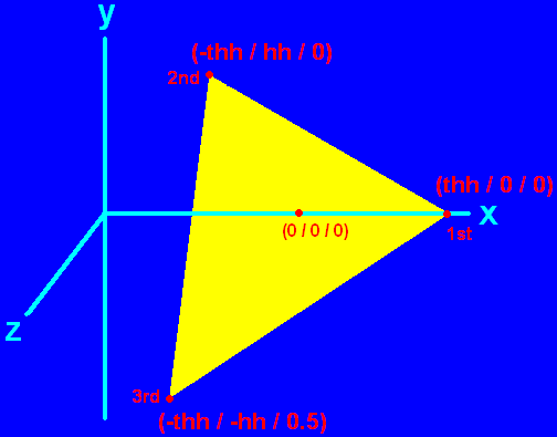
Since I decided to give a rather complicated example for this tutorial (usually OpenGL tutorials explain this by cubes and six quads) I will examine the code here in more detail for the first triangle. If you’ve understood it, you’ll do cubes just by the way :). The coordinates for the first vertex are (thh / 0 / 0), the next vertex are (-thh / hh / 0) and the last vertex are (-thh / -hh / 0.5). The following image will show you how the vertices are placed in the cartesian space.
As you can check quickly, the vertices are indeed placed anticlockwise. The origin of the coordinate system (0 / 0 / 0) is approximately in the center of the triangle, actually it is in the center of the tetrahedron, when it is finished. The first vertex is placed onto the x axis at thh, the half height of the tetrahedron. The second vertex is placed on the opposite x position of the origin at -thh and has a y value of hh, the half height of an equilateral triangle. This point is still in the x/y-plane formed by the x and y axis. The last vertex has a x value of -tth and and y value of -hh, because of the z value of 0.5 this vertex doesn’t belong to the x/y-plane the other two vertices belong to. It is in front of this plane. You’ll notice a slight distorted appearance of the triangle for the third vertex, just as if it would bend towards you, that is because it actually is.
Now try to check if you understand the other vertices coordinates and if you understand why their front and not their back is showing. The loop’s last command is SDL_GL_SWAPBUFFERS which corresponds to SDL_FLIP for a pure SDL scene. It refreshes the scene. In case you have an OpenGL scene you never use SDL_FLIP or SDL_UPDATERECT to refresh the scene!
The loop quits if a key gets pressed. Then SDL and the Pascal program quit as known. If you want to learn OpenGL and its capabilities to a more advaced extend you need to read more professional tutorials related to pure OpenGL programming. As a starting point I’d like to mention NeHe Productions’ OpenGL tutorials, because they are professional and provide example code for JEDI-SDL for several lessons.
This file contains the source code: chap8.pas (right click and “save as”)
This file is the executable: chap8.exe (right click and “save as”)
The final result should look and behave like this: A tetrahedron consisting of four different coloured areas (yellow, cyan, magenta and white) is spinning slowly around itself. When pressing a key in the console the show quits.