Good news, Chapter 10 has been released right now! You ever wondered what to do if you would like to create 3d graphics for a game or application? – Well, you go for modern OpenGL. And SDL 2.0 is probably the best and most convenient way to go for modern OpenGL nowadays, even professionals typically use SDL as powerful assistant for their OpenGL applications. Learn more about the strong relationship between SDL and OpenGL in Chapter 10. – And learn how it’s done, of course ;-).
Chapter 3 got a short explanation now on how to copy the source code of a chapter. In the SDL 1.2 chapters the source code was shipped for each chapter as Pascal file. Nowadays it is much more convenient to grab the source code (or just the desired parts) by copying it directly from the chapter’s source code boxes (in the browser) and paste it whereever it is needed.
The transfer of the old website has been finished. Nearly the complete content is in some way or another transfered to the new page. For example, all tutorial pages (even the old ones) are still available. Some downloads are integrated at the corresponding tutorial pages now, so they are not lost. Some pages are gone, these are Downloads, Tables and Links. These pages are of no benefit anymore since their information are now provided at the corresponding place instead of separate pages. Nevertheless, links trying to access these pages are redirected to the main page to prevent broken links.
No One’s Space got greenlit. This means that this Free Pascal/SDL game will be available in Steam for purchase soon. It demonstrates the power of Free Pascal and SDL.
Small update of some subdomain settings. Subdomain links work again.
This chapter will introduce you on how to combine the SDL library with the famous Open Graphics Library (OpenGL).
What is OpenGL?
OpenGL is the first choice when it comes to platform independent 2d and 3d graphics programming. The emphasis is on graphics programming only though!
Why and when to combine SDL and OpenGL?
SDL is an excellent choice if you need platform independent 2d graphics. OpenGL is capable of 2d graphics, too, but why using the more complicated library if you could use the easy to use SDL library? – And by the way, underneath SDL is actually using OpenGL (or similar libraries depending upon the system) to achieve its hardware accelerated 2d graphics.
However, if your project needs 3d graphics, which isn’t covered by SDL, you can set up your system for this quite easy with SDL. The setup of an OpenGL environment is very easy and platform independent with SDL. Without SDL you would’ve to write different code to set up OpenGL for each operating system. In fact, even professional developers use SDL to set up their OpenGL applications.
Furthermore, since OpenGL is a pure graphics library, any other task is further done by SDL (e.g. keyboard handling, sound,…).
At this point I’d like to quote Klaus Vor der Landwehr (professional developer) from Turtle-Games, who described the relation of SDL and OpenGL in a very clear way.
Although the graphics are often in the foreground, it is for me as a game programmer only one aspect of many with which I have to deal. And the graphics do not even require the most work. OpenAL for example costs much more time and effort if you want to build a 3D sound channel management. And there are many other interfaces. Here is a list of categories in which SDL has been a great help:
As of version 2.0 of OpenGL, the so-called fixed pipeline has been replaced by a programmable pipeline (modern OpenGL). In general, the pipeline makes your input data appear on the screen in a hardware accelerated manner by using your graphics card. For the fixed pipeline it was easy to draw something to the screen but, as the name suggests, it was quite fixed and unflexible. The programmable pipeline which is controlled by a newly introduced shader (script) language is far more flexible, though, the ease is gone :-D.
Anyway, some people refer to OpenGL version 3.0 and up as modern OpenGL. This is because a lot of typical functionality was deprecated as of this version. The backwards compatibility is gone.
In this chapter I will demonstrate how to use SDL 3.0 and up to set up a modern OpenGL environment using some basic shaders. I based the description heavily on an excellent C++ tutorial over at opengl-tutorial.org and their second chapter. You may look for further OpenGL stuff there or have a look at this WikiBook OpenGL Introduction (C++). I’m not aware of OpenGL tutorials for Free Pascal or Delphi treating modern OpenGL (let me know if you know).
OpenGL Pascal units (headers)
Similar to SDL 2.0, you need specific units which translate and connect your code to the OpenGL library. There is a native OpenGL unit GL which covers the main functionality of OpenGL. Additionally for modern OpenGL you need the unit GLext which covers the functionality up to OpenGL version 4.0. These units are shipped right along with the Free Pascal compiler.
In case you are interested in support of OpenGL version 4.4, you should look into the dglOpenGL.pas. This unit is not shipped natively along with the Free Pascal compiler.
Let the fun begin
Let’s have a look at the code:
program chap10_SDL2;
uses Classes, SysUtils, SDL2, GL, GLext;
const
vertexShaderFile = 'VertexShader.txt';
fragmentShaderFile = 'FragmentShader.txt';
triangleData: array[0..8] of GLfloat = ( -1.0, -1.0, 0.0,
1.0, -1.0, 0.0,
0.0, 1.0, 0.0 );
var
sdlWindow1: PSDL_Window;
sdlGLContext1: TSDL_GLContext;
i: Word;
VertexArrayID: GLuint;
triangleVBO: GLuint;
VertexShaderID: GLuint;
VertexShaderCode: PGLchar;
FragmentShaderID: GLuint;
FragmentShaderCode: PGLchar;
ShaderCode: TStringList;
ProgramID: GLuint;
compilationResult: GLint = GL_FALSE;
InfoLogLength: GLint;
ErrorMessageArray: array of GLChar;
begin
if SDL_Init( SDL_INIT_VIDEO ) < 0 then HALT;
//get an OpenGL window and create OpenGL context
sdlWindow1 := SDL_CreateWindow( 'OpenGL window', 50, 50, 500, 500, SDL_WINDOW_OPENGL );
if sdlWindow1 = nil then HALT;
sdlGLContext1 := SDL_GL_CreateContext( sdlWindow1 );
if @sdlGLContext1 = nil then HALT;
//init OpenGL and load extensions
if Load_GL_VERSION_4_0 = false then
if Load_GL_VERSION_3_3 = false then
if Load_GL_VERSION_3_2 = false then
if Load_GL_VERSION_3_0 = false then
begin
writeln(' ERROR: OpenGL 3.0 or higher needed. '); readln;
HALT;
end;
//print out OpenGL vendor, version and shader version
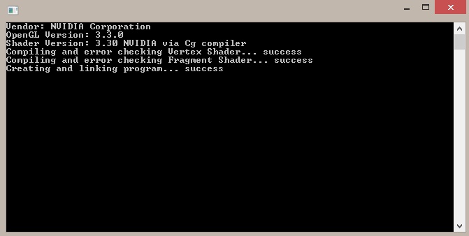
writeln( 'Vendor: ' + glGetString( GL_VENDOR ) );
writeln( 'OpenGL Version: ' + glGetString( GL_VERSION ) );
writeln( 'Shader Version: ' + glGetString( GL_SHADING_LANGUAGE_VERSION ) );
//create Vertex Array Object (VAO)
glGenVertexArrays( 1, @VertexArrayID );
glBindVertexArray( VertexArrayID );
//creating Vertex Buffer Object (VBO)
glGenBuffers( 1, @triangleVBO );
glBindBuffer( GL_ARRAY_BUFFER, triangleVBO );
glBufferData( GL_ARRAY_BUFFER, SizeOf( triangleData ), @triangleData, GL_STATIC_DRAW );
//creating shaders
VertexShaderID := glCreateShader( GL_VERTEX_SHADER );
FragmentShaderID := glCreateShader( GL_FRAGMENT_SHADER );
//load shader code and get PChars
ShaderCode := TStringList.Create;
ShaderCode.LoadFromFile( VertexShaderFile );
VertexShaderCode := ShaderCode.GetText;
if VertexShaderCode = nil then HALT;
ShaderCode.LoadFromFile( FragmentShaderFile );
FragmentShaderCode := ShaderCode.GetText;
if FragmentShaderCode = nil then HALT;
ShaderCode.Free;
//compiling and error checking vertex shader
write('Compiling and error checking Vertex Shader... ' );
glShaderSource( VertexShaderID, 1, @VertexShaderCode, nil );
glCompileShader( VertexShaderID );
glGetShaderiv( VertexShaderID, GL_COMPILE_STATUS, @compilationResult );
glGetShaderiv( VertexShaderID, GL_INFO_LOG_LENGTH, @InfoLogLength );
if compilationResult = GL_FALSE then
begin
writeln( 'failure' );
SetLength( ErrorMessageArray, InfoLogLength+1 );
glGetShaderInfoLog( VertexShaderID, InfoLogLength, nil, @ErrorMessageArray[0] );
for i := 0 to InfoLogLength do write( String( ErrorMessageArray[i] ) );
writeln;
end else writeln( 'success' );
//compiling and error checking fragment shader
write('Compiling and error checking Fragment Shader... ' );
glShaderSource( FragmentShaderID, 1, @FragmentShaderCode, nil );
glCompileShader( FragmentShaderID );
glGetShaderiv( FragmentShaderID, GL_COMPILE_STATUS, @compilationResult );
glGetShaderiv( FragmentShaderID, GL_INFO_LOG_LENGTH, @InfoLogLength );
if compilationResult = GL_FALSE then
begin
writeln( 'failure' );
SetLength( ErrorMessageArray, InfoLogLength+1 );
glGetShaderInfoLog( VertexShaderID, InfoLogLength, nil, @ErrorMessageArray[0] );
for i := 0 to InfoLogLength do write( String( ErrorMessageArray[i] ) );
writeln;
end else writeln( 'success' );
//creating and linking program
write('Creating and linking program... ' );
ProgramID := glCreateProgram();
glAttachShader( ProgramID, VertexShaderID );
glAttachShader( ProgramID, FragmentShaderID );
glLinkProgram( ProgramID );
glGetShaderiv( ProgramID, GL_LINK_STATUS, @compilationResult );
glGetShaderiv( ProgramID, GL_INFO_LOG_LENGTH, @InfoLogLength );
if compilationResult = GL_FALSE then
begin
writeln( 'failure' );
SetLength( ErrorMessageArray, InfoLogLength+1 );
glGetShaderInfoLog( VertexShaderID, InfoLogLength, nil, @ErrorMessageArray[0] );
for i := 0 to InfoLogLength do write( String( ErrorMessageArray[i] ) );
writeln;
end else writeln( 'success' );
for i := 0 to 400 do
begin
glClearColor( 0.0, 1.0-i/400, 0.0+i/400, 1.0 );
glClear( GL_COLOR_BUFFER_BIT );
glUseProgram( ProgramID );
glEnableVertexAttribArray( 0 );
glBindBuffer( GL_ARRAY_BUFFER, triangleVBO );
glVertexAttribPointer( 0, 3, GL_FLOAT, GL_FALSE, 0, nil );
glDrawArrays( GL_TRIANGLES, 0, 3 );
glDisableVertexAttribArray( 0 );
SDL_Delay( 20 );
SDL_GL_SwapWindow( sdlWindow1 );
end;
//clean up
glDetachShader( ProgramID, VertexShaderID );
glDetachShader( ProgramID, FragmentShaderID );
glDeleteShader( VertexShaderID );
glDeleteShader( FragmentShaderID );
glDeleteProgram( ProgramID );
StrDispose( VertexShaderCode );
StrDispose( FragmentShaderCode );
glDeleteBuffers( 1, @triangleVBO );
glDeleteVertexArrays( 1, @VertexArrayID );
SDL_GL_DeleteContext( sdlGLContext1 );
SDL_DestroyWindow( sdlWindow1 );
SDL_Quit;
end.
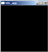
Wow that is a lot of code. What you will get is this:
The background will change slowly from green to blue. And you will get this:
The vendor, OpenGL version and shader version information will be different according to your system. Also, if your system doen’t support the needed OpenGL version you’ll not have “success” but rather “failure” after the compiling and linking processes. Additional information may be shown then.
The program is called “chap10_SDL2” for obvious reason.
Additionally to the SDL2 unit we load the native FPC units Classes (for TStringList support), SysUtils (for PChar functions) and GL and GLext for OpenGL support.
Thre are three constants declared. The first two are defined as the filenames of the so-called shader source files. Basically they are simple text files which contain a script. More about shaders and the script later. The third is an array of nine GLfloat values. GLfloat is the OpenGL float variable type which in fact is translated as Pascal’s Single type. In short, these nine values describe three points in 3d space which, if connected, form a triangle. More about this later.
The first variable “sdlWindow1” is well known from previous chapters. Any variable to follow is new though. Most of them are related to OpenGL.
“sdlGLContext1” is of type TSDL_GLContext needed to create a so-called OpenGL context. In fact, this variable type is provided by SDL and a key type to set up an OpenGL conext in a simple and cross-platform manner.
The variable “i” is a simple Word variable for counting purposes.
OpenGL’s Integers and Strings
Most of the following variables are either of type GLuint or of type PGLchar. The last variable is an dynamic array of GLchars. Their specific meaning will be discussed later but GLuint is the OpenGL unsigned integer type (no negative values) which translates to Pascal’s Cardinal/Longword type. Text handling in OpenGL works by null-terminated strings of type PGLchar which translate to Pascal’s PChar. GLchar translates to Char then, obviously.
At this point you may wonder why as for SDL the null-terminated strings are used instead of simple strings (see Chapter 7 for the PAnsiChar variable type discussion). The answer again is that OpenGL is based upon C which handles strings this way. PChar equals PAnsiChar by the way.
The remaining variables “ShaderCode” of type TStringList will be used to handle the shader text files. “compilationResult” and “InfoLogLength” are of GLint type. In contrast to GLuint they allow for negative values.
begin
  if SDL_Init( SDL_INIT_VIDEO ) < 0 then HALT;

  //get an OpenGL window and create OpenGL context
  sdlWindow1 := SDL_CreateWindow( 'OpenGL window', 50, 50, 500, 500, SDL_WINDOW_OPENGL );
  if sdlWindow1 = nil then HALT;

  sdlGLContext1 := SDL_GL_CreateContext( sdlWindow1 );
  if @sdlGLContext1 = nil then HALT;

  //init OpenGL and load extensions
  if Load_GL_VERSION_4_0 = false then
    if Load_GL_VERSION_3_3 = false then
      if Load_GL_VERSION_3_2 = false then
        if Load_GL_VERSION_3_0 = false then
        begin
          writeln(' ERROR: OpenGL 3.0 or higher needed. '); readln;
          HALT;
        end;

  //print out OpenGL vendor, version and shader version
  writeln( 'Vendor: ' + glGetString( GL_VENDOR ) );
  writeln( 'OpenGL Version: ' + glGetString( GL_VERSION ) );
  writeln( 'Shader Version: ' + glGetString( GL_SHADING_LANGUAGE_VERSION ) );
First SDL2 is initilized as known. “sdlWindow1” is created as known by SDL_CreateWindow. Be careful though, in order to work with OpenGL the flag SDL_WINDOW_OPENGL has to be set!
SDL 2.0 and the OpenGL context
An OpenGL context is kind of an abstract name. It doesn’t represents just a window, even though it is created from a SDL2 window, but rather it contains everything (including the window information) that is related to this OpenGL context. The OpenGL context is therefore kind of “broader” than just a window, that is why it is called context rather than just a OpenGL window.
The function to create an OpenGL context from a SDL2 window is:
function SDL_GL_CreateContext(window: PSDL_Window): TSDL_GLContext
So, it is simple as that, just use the SDL2 window as argument and voila, you’ll get a OpenGL context, platform-independent. That is why everybody loves SDL2 to work with OpenGL. Note that the returned Context isn’t a pointer but an actual instance. So to error check against nil you need to refer to the instance’s addresse by the @ operator.
OpenGL version check and initialization
The nested if-then-statements check if at least version 3.0 of OpenGL is installed. If so, the highest available version is loaded. If not, the program is stopped and returns a text message.
If your hardware doen’t support OpenGL 3.0 or higher you should try to update your graphics driver. There is a good chance that you are able to use OpenGL 3.0 or higher then. Anyway, if the upgrade doesn’t work out or you wouldn’t want to update, you may have a look into the JEDI-SDL Chapter about OpenGL, there the old OpenGL is treated (although that chapter treats SDL 1.2, it shouldn’t be too hard to make it work with SDL 2.0 with minor changes).
Next there are three text messages printed out. These present the Vendor, the OpenGL version and the Shading language version. To get them in a readable form you need to transform the constants into strings by function glGetString. Let’s have a look at the command window again:
Have a look at the first three lines and you see what it could look like.
If you are new to OpenGL, OpenGL as kind of machine with many switches. Each switch
Briefly, a Vertex Array Object (VAO) is a specific OpenGL object which contains important settings (e.g. format of vertex data) and references to other objects, including Vertex Buffer Objects (VBO). Notice, it doesn’t store the object’s data (content) itself, it just stores the reference to these objects.
The Vertex Buffer Object (VBO) contains the actual data (content). In the example case these are three vertices, each described by three float point values in cartesian space.
OpenGL Object name or ID
Because it is important to understand, in contrast to SDL where objects usually are directly submitted to a function by its pointer reference, in OpenGL you have a so-called OpenGL Object name, which actually is an integer value of GLuint type. Therefore ID is a suitable name, too. Let’s see how this works:
The VAO is created by function glGenVertexArrays( number of VAO names, pointer to VAO names array ). The first parameter determines how many VAO names I’d like to create. We just need 1. The second parameter asks for a pointer to an array of VAO names. Since VAO names are just simple GLuints, it is a simple array of GLuints. Anyway, since we just need one, a pointer to a simple GLuint variable will be suitable, too. In our case that is “VertexArrayID”. To bind (“activate”) the corresponding VAO to the OpenGL context, the function glBindVertexArray( name of VAO ) is used. The argument is the name of the VAO we just created in “VertexArrayID”.
Similar to the VAO, the VBO is created by function glGenBuffers( number of VBO names, pointer to VBO names array ). Again, we just need 1 VBO whose name should be returned to “triangleVBO”. This variable just stores an ID (object name) of GLuint type.
From the naming of “triangleVBO” it is clear to us what we intent here (representing a triangle by three vertices), anyway, how should OpenGL know? – We explain the meaning of this buffer object to OpenGL by using glBindBuffer ( target, VBO name ). There are numerous options as target but GL_VERTEX_BUFFER is the right choice here.
The actual VBO is created by glBufferData( target, size of object’s data store in bytes, pointer to data to be copied into VBO, expected usage ). This functions takes four arguments. The target is GL_VERTEX_BUFFER again. The size of the VBO’s data store in bytes is determined by Pascal’s SizeOf function applied to “triangleData”. The “triangleData” constant also holds the data to be copied into the VBO, so its pointer is suitable as the third argument. Since we are not going to change the data a lot, we should use GL_STATIC_DRAW as fourth argument.
If you are a newcomer to OpenGL, don’t worry if you are confused the first time. Most people are. And now it may even get worse :-(.
Shaders and OpenGL Shading Language
When starting with modern OpenGL the so-called Shaders are talked about a lot. Shaders are scripts written in a C-like script language called OpenGL Shading Language (GLSL). These scripts are compiled at runtime and influence the way how the graphics data is processed at certain steps in the so-called rendering pipeline of OpenGL. In fact, you can create rather complex and special effects with shaders without even changing one line of code of your source code.
Vertex Shader and Fragment Shader
There are two Shaders that are crucial and have to be set up to work with modern OpenGL. They are called Vertex Shader and Fragment Shader. There are more Shaders not covered here, though. Each type of Shader influences different aspects of the rendering.
The Vertex Shader is the first Shader program executed in the rendering pipeline. Every vertex is “put through” the Vertex Shader program and processed accordingly, hence the name. Often this Shader is used to perform transformation operations. The Shader script used in this tutorial is shown next:
This GLSL source code is saved into a file VertexShader.txt and located in the same directory as the source code of this chapter’s example source code. I’m not going to explain this GLSL code in detail here, but a detailed explanation is found over at opengl-tutorial.org Chapter 2 where I got this Shader code from, by the way.
The Frgament Shader is the last Shader program executed in the renderin pipeline. The so-called rasterization process produces fragments. Every fragment is “put through” the Fragment Shader program and processed accordingly. The Shader script used for the Fragment Shader is:
#version 330 core

out vec3 color;

void main(){
   color = vec3(1,0,0);
 }
This code is in file FragmentShader.txt and located in the same directory as the VertexShader.txt. The detailed explanation is found over at opengl-tutorial.org Chapter 2 again. Anyway, you’ll notice that there is a “color” variable (three component vector). As you see, it sets the (red,green,blue) values for the fragments to (1,0,0) which means red should be the result, red = 100%, green and blue = 0%. You may play around with these values.
  //creating shaders
  VertexShaderID := glCreateShader( GL_VERTEX_SHADER );
  FragmentShaderID := glCreateShader( GL_FRAGMENT_SHADER );

  //load shader code and get PChars
  ShaderCode := TStringList.Create;
  ShaderCode.LoadFromFile( VertexShaderFile );
  VertexShaderCode := ShaderCode.GetText;
  if VertexShaderCode = nil then HALT;
  ShaderCode.LoadFromFile( FragmentShaderFile );
  FragmentShaderCode := ShaderCode.GetText;
  if FragmentShaderCode = nil then HALT;
  ShaderCode.Free;
Both Shaders are created by function glCreateShader( Shader type ). It returns the reference (or name) as GLuint as seen before for the VAO and VBO. We store them in the VertexShaderID and FragmenShaderID, respecitvely.
The next part is about loading the source code from the two Shader files (VertexShader.txt, FragmentShader.txt) and converting them to be used with OpenGL. First a “ShaderCode” variable of TStringList type is created. Its LoadFromFile method let us load the file contents into the variable conveniently. First for the Vertex Shader, whose file name is stored in constant “VertexShaderFile”. The variable “VertexShaderCode” is of type PGLchar, which is the way OpenGL handles strings. Since PGLchar is of type PChar anyway, the method GetText is perfectly suitable here to convert the source code string into a null-terminated array of chars. Finally, there is a simple check if the PGLchars are empty (nil), which shouldn’t be the case if the source code is pointed to as expected.
Exactly the same is done for the FragmentShader and the source code associated with “FragmentShaderCode”.
Finally, the dummy variable “ShaderCode” is free’d.
  //compiling and error checking vertex shader
  write('Compiling and error checking Vertex Shader... ' );
  glShaderSource( VertexShaderID, 1, @VertexShaderCode, nil );
  glCompileShader( VertexShaderID );

  glGetShaderiv( VertexShaderID, GL_COMPILE_STATUS, @compilationResult );
  glGetShaderiv( VertexShaderID, GL_INFO_LOG_LENGTH, @InfoLogLength );
  if compilationResult = GL_FALSE then
  begin
    writeln( 'failure' );
    SetLength( ErrorMessageArray, InfoLogLength+1 );
    glGetShaderInfoLog( VertexShaderID, InfoLogLength, nil, @ErrorMessageArray[0] );
    for i := 0 to InfoLogLength do write( String( ErrorMessageArray[i] ) );
    writeln;
  end else writeln( 'success' );

  //compiling and error checking fragment shader
  write('Compiling and error checking Fragment Shader... ' );
  glShaderSource( FragmentShaderID, 1, @FragmentShaderCode, nil );
  glCompileShader( FragmentShaderID );

  glGetShaderiv( FragmentShaderID, GL_COMPILE_STATUS, @compilationResult );
  glGetShaderiv( FragmentShaderID, GL_INFO_LOG_LENGTH, @InfoLogLength );
  if compilationResult = GL_FALSE then
  begin
    writeln( 'failure' );
    SetLength( ErrorMessageArray, InfoLogLength+1 );
    glGetShaderInfoLog( VertexShaderID, InfoLogLength, nil, @ErrorMessageArray[0] );
    for i := 0 to InfoLogLength do write( String( ErrorMessageArray[i] ) );
    writeln;
  end else writeln( 'success' );
To associate the source code we stored in “VertexSourceCode” to “VertexShaderID” of GLuint type, the function glShaderSource( Shader reference, number of array elements, pointer to array of source code PGLchars, pointer to array of lengths ). The Vertex Shader reference is stored in “VertexShaderID” which is the first argument. We just have one source code, so the second argument is 1. The source code is stored VertexShaderCode, and its pointer is addressed by @VertexShaderCode as the third argument. As seen before, since we just have one element here, it is not necessary to have really an array. The fourth parameter allows for some length specification, but if set to nil it expects null-terminated arrays of chars.
The compilation is straight forward done by glCompileShader( Shader reference ). It is really advised to to error checking here, that is why it is shown how to do that. The function glGetShaderiv( Shader reference, object parameter, pointer of correct type for return value ) is used to request information about objects. First we like to know if the compilation was successful. The Shader reference is stored in “VertexShaderID”, the object parameter is GL_COMPILE_STATUS. This will return a GLint value, which can be interpreted as GL_FALSE or GL_TRUE. The result is stored in “compilationResult” by using its pointer (@compilationResult) as argument.
Right after that we request the length of the information log by GL_INFO_LOG_LENGTH. It will be greater than 0 if some information were logged (probably an error occured on compilation then). The result is returned to “InfoLogLength” by its pointer @InfoLogLength.
If an error occurs, “compilationResult” is GL_FALSE. In this case “failure” along with more specific information is printed out. I’m not going into detail here, since this shouldn’t happen. Otherwise (and that should be the case), “success” is printed out.
The very same way the Fragment Shader is compiled and checked.
  //creating and linking program
  write('Creating and linking program... ' );
  ProgramID := glCreateProgram();
  glAttachShader( ProgramID, VertexShaderID );
  glAttachShader( ProgramID, FragmentShaderID );
  glLinkProgram( ProgramID );

  glGetShaderiv( ProgramID, GL_LINK_STATUS, @compilationResult );
  glGetShaderiv( ProgramID, GL_INFO_LOG_LENGTH, @InfoLogLength );
  if compilationResult = GL_FALSE then
  begin
    writeln( 'failure' );
    SetLength( ErrorMessageArray, InfoLogLength+1 );
    glGetShaderInfoLog( VertexShaderID, InfoLogLength, nil, @ErrorMessageArray[0] );
    for i := 0 to InfoLogLength do write( String( ErrorMessageArray[i] ) );
    writeln;
  end else writeln( 'success' );
The shaders have to be attached and linked by a Shader program. A Shader program is created by glCreateProgram(). The parenthesis are important here. It returns an reference of GLuint type which is stored in ProgramID.
The Shaders are attached to this Shader program by glAttacheShader( Program reference, Shader reference ). The program is linked by glLinkProgram( Program reference ). The reference for the Shader program is “ProgramID”. The references for the Shaders are “VertexShaderID” and “FragmentShaderID”, respectively.
By complete analogy to the error checking for the Shader compilation, the Shader program linking is checked. Anyway, instead of GL_COMPILE_STATUS, GL_LINK_STATUS is used.
  for i := 0 to 400 do
  begin
    glClearColor( 0.0, 1.0-i/400, 0.0+i/400, 1.0 );
    glClear( GL_COLOR_BUFFER_BIT );
    glUseProgram( ProgramID );
    glEnableVertexAttribArray( 0 );
    glBindBuffer( GL_ARRAY_BUFFER, triangleVBO );
    glVertexAttribPointer( 0, 3, GL_FLOAT, GL_FALSE, 0, nil );
    glDrawArrays( GL_TRIANGLES, 0, 3 );
    glDisableVertexAttribArray( 0 );
    SDL_Delay( 20 );
    SDL_GL_SwapWindow( sdlWindow1 );
  end;
The for-loop counts from 0 to 400. Within each cycle it first changes the background color by glClearColor( red, green, blue, alpha ). Red and alpha are constant, green and blue are varied each cycle dependend upon variable i. This makes the background slowly changing from green to blue, feel free to play around with the rgba values. To actually clear the color buffer glClear( buffer ) with GL_COLOR_BUFFER_BIT as argument is used.
glUseProgram( Shader program reference ) is used to apply the Shader program to the rendering state. “ProgramID” is the Shader program reference in the example code.
glEnableVertexAttribArray( array index ) is used in order to make the attribute array available for rendering by glDrawArrays. The index is 0 here. The “triangleVBO” is bound by glBindBuffer( target, buffer ) to the GL_BUFFER_ARRAY target to change attribute data of said VBO. Latter is done by glVertexAttribPointer( index, size, type, normalized, stride, offset of first component ) with the given arguments. Hence, the index is 0, 3 components per generic vertex attribute, each of float point type (thus, GL_FLOAT), not normalized (thus GL_FALSE), no strides between vertex attributes, no offset for the first component.
The rendering is done by glDrawArrays( type of primitive, starting index, number of elements ). The type of primitive is a triangle, hence GL_TRIANGLES is the first argument. We start at the very beginning, so index is 0. We have 3 sequential elements (vertices).
glDisableVertexAttribArray( array index ) is the counter function to glEnableVertexAttribArray( array index ), obviously. It disables the vertex attribute array.
SDL_Delay delays the loop by 20 milliseconds.
The procedure
procedure SDL_GL_SwapWindow(window: PSDL_Window)
is used to actually display the rendering result to the the window “sdlWindow1”. Keep in mind that this window has to be initialized as an OpenGL window. This procedure is comparable to SDL’s SDL_RenderPresent.
For the clean up, the shaders have to be detached from the shader program by glDetachShader( program, shader ). After that they can be deleted by glDeleteShader( shader ), and the program by glDeleteProgram( program ).
The shader script PChars are disposed by StrDispose( PChar ).
The VBO and the vertex array have to be free’d by glDeleteBuffers( number of buffer objects, pointer to array of buffers ) and glDeleteVertexArrays( number of VAOs, pointer to array of VAOs ) respectively. The first parameter is the number of objects to be deleted, which is 1 in both our cases.
Displaying of textures as discussed in previous chapters are sometimes accompanied by drawing operations. For some applications and games drawing operations are even essential, e.g. you need to draw buttons of dynamic dimension in your application. Discussion of a more detailed case is found right after the code example.
Supported Primitives: Points, Lines, Rectangles
SDL2 supports natively the drawing of
Points
Lines
Rectangles (outline only)
Filled Rectangles.
Drawing in SDL 2.0
Now lets jump right into the code:
program Chapter5_SDL2;

uses SDL2;

var
  i: Integer;
  sdlWindow1: PSDL_Window;
  sdlRenderer: PSDL_Renderer;
  sdlRect1: TSDL_Rect;
  sdlPoints: array[0..499] of TSDL_Point;

begin
  //initilization of video subsystem
  if SDL_Init(SDL_INIT_VIDEO) < 0 then
    halt;

  sdlWindow1 := SDL_CreateWindow('Window1', 50, 50, 500, 500, SDL_WINDOW_SHOWN);
  if sdlWindow1 = nil then
    halt;

  sdlRenderer := SDL_CreateRenderer(sdlWindow1, -1, 0);
  if sdlRenderer = nil then
    halt;

  //render and show cleared window with background color
  SDL_SetRenderDrawColor(sdlRenderer, 0, 255, 255, 255);
  SDL_RenderClear(sdlRenderer);
  SDL_RenderPresent(sdlRenderer);
  SDL_Delay(1000);

  //render and show a line
  SDL_SetRenderDrawColor(sdlRenderer, 255, 0, 0, 255);
  SDL_RenderDrawLine(sdlRenderer, 10, 10, 490, 490);
  SDL_RenderPresent(sdlRenderer);
  SDL_Delay(1000);

  //render and draw points diagonally with distance between each other
  SDL_SetRenderDrawColor(sdlRenderer, 0, 0, 0, 255);
  for i := 0 to 47 do
    SDL_RenderDrawPoint(sdlRenderer, 490-i*10, 10+i*10);
  SDL_RenderPresent(sdlRenderer);
  SDL_Delay(1000);

  //prepare, render and draw a rectangle
  sdlRect1.x := 260;
  sdlRect1.y := 10;
  sdlRect1.w := 230;
  sdlRect1.h := 230;
  SDL_SetRenderDrawColor(sdlRenderer, 0, 255, 0, 255);
  SDL_RenderDrawRect(sdlRenderer, @sdlRect1);

  //relocate, render and draw the rectangle
  sdlRect1.x := 10;
  sdlRect1.y := 260;
  SDL_SetRenderDrawBlendMode(sdlRenderer, SDL_BLENDMODE_BLEND);
  SDL_SetRenderDrawColor(sdlRenderer, 0, 0, 255, 128);
  SDL_RenderFillRect(sdlRenderer, @sdlRect1);
  SDL_RenderPresent(sdlRenderer);
  SDL_Delay(1000);

  //prepare, render and draw 500 points with random x and y values
  Randomize;
  for i := 0 to 499 do
  begin
    sdlPoints[i].x := Random(500);
    sdlPoints[i].y := Random(500);
  end;
  SDL_SetRenderDrawColor(sdlRenderer, 128, 128, 128, 255);
  SDL_RenderDrawPoints(sdlRenderer, sdlPoints, 500);
  SDL_RenderPresent(sdlRenderer);
  SDL_Delay(3000);

  //clean memory
  SDL_DestroyRenderer(sdlRenderer);
  SDL_DestroyWindow (sdlWindow1);

  //shut down SDL2
  SDL_Quit;
end.
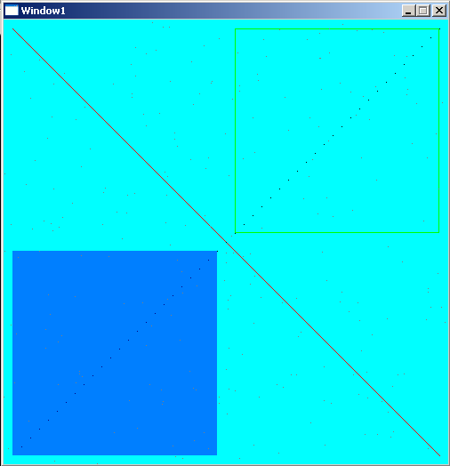
Wow, that looks like a big load of new functions, but I promise, drawing in SDL2 is very simple. What the executed program will look like is shown in the following screenshot.
Now, let’s have a closer look to the first lines of code.
program Chapter5_SDL2;

uses SDL2;

var
  i: Integer;
  sdlWindow1: PSDL_Window;
  sdlRenderer: PSDL_Renderer;
  sdlRect1: TSDL_Rect;
  sdlPoints: array[0..499] of TSDL_Point;
The program is called “Chapter5_SDL2”. We will need a counter variable “i” of native Pascal type integer later. We need a window and a renderer and call them “sdlWindow1” and “sdlRenderer” as known from the previous chapters. Next we declare a variable “sdlRect1” which is of type TSDL_Rect. The same is true for “sdlPoints” which is an array of 500 elements of type TSDL_Point.
begin
  //initilization of video subsystem
  if SDL_Init(SDL_INIT_VIDEO) < 0 then
    halt;

  sdlWindow1 := SDL_CreateWindow('Window1', 50, 50, 500, 500, SDL_WINDOW_SHOWN);
  if sdlWindow1 = nil then
    halt;

  sdlRenderer := SDL_CreateRenderer(sdlWindow1, -1, 0);
  if sdlRenderer = nil then
    halt;
Nothing new here, we initilize SDL2, create a window with 500 pixels width and 500 pixels height and associate the renderer with this window.
Colours, alpha value and RGB(A) notation in SDL 2.0
  //render and show cleared window with background color
  SDL_SetRenderDrawColor(sdlRenderer, 0, 255, 255, 255);
  SDL_RenderClear(sdlRenderer);
  SDL_RenderPresent(sdlRenderer);
  SDL_Delay(1000);
Now we have something new here, SDL_SetRenderDrawColor() sets a colour for drawing operations, just as if you choose for a pencil colour to draw something. This function doesn’t draw anything though. It returns 0 on success and the negative error code on failure.
First you need to set the renderer for which this drawing colour is meant. After that you have to set the colours red, green, blue and the alpha value. They can range from 0 to 255 (integer values only). Think in terms of 255 being 100% and 0 being 0% of that colour or the alpha value. As a start let’s neglect the alpha value.
If you like to have a red colour, you need to set the value for the red colour high, e.g. 100%, the maximum value is 255, and since you don’t want to mix in green and blue, they get the minimum value of 0 (hence 0%). Setting up red therefore corresponds to 255/0/0 in terms of r/g/b. For comparision, 0/255/0 will lead to green, 255/255/255 is white and 0/0/0 is black, and so on. In the example code we used 0/255/255 which leads to cyan (mixing up green and blue additively). With these three values you can generate every colour possible.
So what is the meaning of the alpha value then? Well, it determines the transparency. 255 means fully opaque and 0 means full transparency. This is very important for blend effects in computer graphics and will be demonstrated later on in the code. By the way, instead of 255 you could use SDL_ALPHA_OPAQUE. If you count the alpha value also as colour variation you have 4.29 billion different possibilities.
Setting up a background in SDL2
The function SDL_RenderClear() is for clearing the screen with the drawing colour. As argument you just need to tell the renderer. It is simple as that :-). Since we set the drawing colour to cyan before, the screen will be cleared with a cyan colour.
SDL_RenderClear(renderer: PSDL_Renderer): SInt32
This function will return 0 on success and a negative error code on failure. The cleared screen will be shown for one second by SDL_RenderPresent() and SDL_Delay(). These two procedures are known from the previous chapter.
Drawing Lines and Points in SDL2
  //render and show a line
  SDL_SetRenderDrawColor(sdlRenderer, 255, 0, 0, 255);
  SDL_RenderDrawLine(sdlRenderer, 10, 10, 490, 490);
  SDL_RenderPresent(sdlRenderer);
  SDL_Delay(1000);
Now we change the drawing colour by SDL_SetRenderDrawColor() to red and use SDL_RenderDrawLine() to draw a simple line.
Again you need the renderer, which is “sdlRenderer” in our case. After that you specify the x/y coordinates where the line should begin and then the x/y coordinates where the line should end. Remember that the origin 0/0 is at the top left corner of the window. The coordinates 10/10 mean to start at the point ten pixels to the right and ten pixel to the bottom relative to the origin. Thus, the coordinates 490/490 for the second point will lead to a diagonal line across the window. This diagonal line will be 10 pixels short with respect to the window edge. This function returns 0 on success and a negative error code on failure.
After that again we ask to render this line to the screen by SDL_RenderPresent() and wait one second by SDL_Delay().
  //render and draw points diagonally with distance between each other
  SDL_SetRenderDrawColor(sdlRenderer, 0, 0, 0, 255);
  for i := 0 to 47 do
    SDL_RenderDrawPoint(sdlRenderer, 490-i*10, 10+i*10);
  SDL_RenderPresent(sdlRenderer);
  SDL_Delay(1000);
Now we change the colour to black and draw some points by the function SDL_RenderDrawPoint(). It is nearly identical to SDL_RenderDrawLine() but instead of four coordinates you need just two coordinates where the point should be drawn.
This function returns 0 on success and the negative error code on failure.
I thought it would be nice to have more than just one point to be drawn, so the function is used in a for-loop to draw altogether 48 points. Here we need the counter variable “i”. Maybe you can guess from the code where the points are and how they are arranged, if not, just run the code ;-). Finally the result is rendered to the screen by SDL_RenderPresent() and the program waits one second by SDL_Delay().
It requires the renderer, which is “sdlRenderer” for us and a PSDL_Rect , thus we use the @ operator for the declared rectangle of TSDL_Rect type to get its pointer value. This function returns 0 on success and the negative error code on failure. Notice, we neither render the result to the screen now nor do we delay here. Anyway, we want a second rectangle! 🙂
We change the rectangles x/y coordinates for the second rectangle but keep its width and height. What we are looking for is a filled rectangle that has some transparency. Until now we always used 255 (opaque) as alpha value. We set the colour to draw the second rectangle to blue by SDL_SetRenderDrawColor(). Notice that the fourth value is 128 (half-transparent) instead of 255 (opaque). So everything behind the blue rectangle, e.g. the cyan background, should therefore shine through. To generate a filled rectangle SDL_RenderFillRect() is used:
The renderer and the rectangle of type PSDL_Rect are the parameters of this function. So we use “sdlRenderer” and “sdlRect1” (with the @ operator) again to draw the rectangle. This function returns 0 on success and the negative error code on failure.
The Blend Mode in SDL 2.0
But to be honest, even if you change the alpha value it will be opaque. This is because the blend mode is set to SDL_BLENDMODE_NONE by default. We need to change this to be able to use the alpha value as desired. SDL_SetRenderDrawBlendMode() is what we are looking for:
First the renderer for which the blend mode has to be set is chosen. In our case it is “sdlRenderer” again. Then there are four blend modes available. Their description is taken from the official SDL2 Wiki.
SDL_BLENDMODE_NONE
no blending
dstRGBA = srcRGBA
SDL_BLENDMODE_BLEND
alpha blending
dstRGB = (srcRGB * srcA) + (dstRGB * (1-srcA))
dstA = srcA + (dstA * (1-srcA))
SDL_BLENDMODE_ADD
additive blending
dstRGB = (srcRGB * srcA) + dstRGB
dstA = dstA
SDL_BLENDMODE_MOD
color modulate
dstRGB = srcRGB * dstRGB
dstA = dstA
We are looking for alpha blending, so we use SDL_BLENDMODE_BLEND as argument for the blend mode. This function returns 0 on success and the negative error code on failure.
After doing so the result is rendered to the screen by SDL_RenderPresent() and shown for one second by SDL_Delay(). Both rectangles, the green one and the half-transparent blue one appear at the same time.
Spread Points Randomly using PSDL_Point
  //prepare, render and draw 500 points with random x and y values
  Randomize;
  for i := 0 to 499 do
  begin
    sdlPoints[i].x := Random(500);
    sdlPoints[i].y := Random(500);
  end;
Randomize is a Free Pascal procedure (from system unit) to initilize the random number generator. Imagine this as shaking the dice.
Let’s have a look at TSDL_Point. It is just a record of this structure:
As expected, the TSDL_Point record has two values, the x/y coordinates of the point. Notice how PSDL_Point is just a pointer to it. Free Pascal’s Random() function generates random numbers between 0 and the number which is used as argument substracted by one. So we generate 500 times a random x and y value between 0 and 499 and save them into the 500 SDL_Point records.
This function returns 0 on success and the negative error code on failure. First you need to set the renderer, then just a pointer to an array of TSDL_Point (returned by simply passing the array’s name) and finally the number of points. The latter should be consistent with the array. So, if your array has 500 elements, the count should be 500 at maximum. Notice how we are not using a loop here to draw all 500 points by calling a certain function 500 times. Instead we just pass an array of points once. This way we save a lot of time at runtime, especially if you think of a real application where even more points have to be drawn. There are similar functions for lines, rectangles and filled rectangles. They are not used in the example but it may be interesting to know, so here they are:
To put your array in the heap, you would want to use an array of PSDL_Point instead of an array of TSDL_Point. For some reason it doesn’t seem to work well with the SDL_RenderDrawPoints() function. This means, instead of, let’s say 500 points just a quarter of all points (125 in the example) is shown unless you specifiy the count as being four times greater (2000 in the example). The reason behind this, is not clear to me.
Case: Drawing for Dynamic Colouring
As an example when drawing can be very helpful, think of the following situation. You create a game, let’s say a racing game. There are different players. Of course, each player’s car has to have a different colour. There are generally two ways to achieve this:
1) You create several images with differently coloured cars and store them on your harddrive.
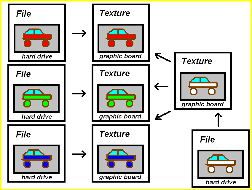
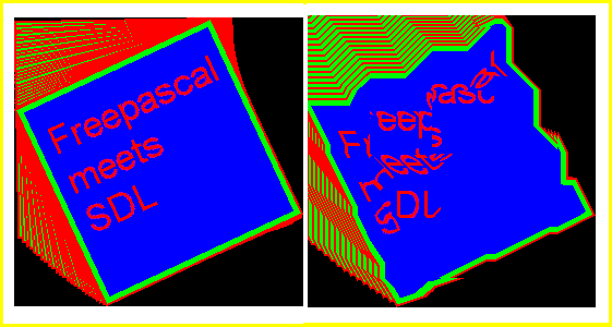
This is perfectly okay if you have a small number of cars (and colours) to be chosen. But what if you want the player to choose from a large variety of colours, 100 colours or more, or what if you want to let the player to choose the colour of his car by himself? Notice, in case of 16 bit colouring that means 65536 possibilities after all! Would you want to create that many images? In case of 32 bit colouring you have fantastic 4.29 billion colours!! Amazing, but you will never be able to create so many images in just one human being’s life. Furthermore, this would take up a lot of hard drive memory (4.29 billion times the file size of the car image) for just a simple car racing game. Look at the following image. It contains the discussed method from left to the middle. On the right to the middle is the solution :-).
Instead of having each car coloured as an image file, why not using just one image file of a car without colouring? It is kind of a template. Now you can easily ask the player what colour he prefers (and he may pick from 4.29 billion colours if necessary), and then you simply colour the car on the fly. This is the second way:
2) You create one template image on your harddrive and colour it during runtime of the program.
This is just one example where drawing is very helpful.
Understanding Colours in Computer Graphics
The colour is composed of four components, RGBA, that is red, green, blue and the alpha value. The physical screen consists of many small units. Every unit itself consists of three different coloured lights. These colours are red, green and blue. If you mix them up, you can get every other colour. These colours are mixed up additively. For example if you mix red and green you get yellow. For three colours that can be mixed with each other, there are eight combinations possible which lead to different colours (RGB, RG, RB, R, GB, G, B, all lights off). If you mix red, green and blue (all lights on, RGB), you get white, and if all lights are off, you get black. Some may say, white and black are no colours at all. Well, that is right but doesn’t matter here and to keep simpliness I will talk of colours even if I talk of black and white.
Your screen definitvly has more than eight colours, doesn’t it? The reason is, your screen isn’t just able to switch lights on or off. Besides it is able to differ the intensities of the lights. The more intensity levels you have the more colours you can display. The case that you have eight colours as discussed before means that you just have one intensity level, on or off. If your screen is in 8 bit mode every pixel on the screen has the possibility to display 2 power 8 colours. That are 256 different colours. Every of the three lights has therefore a certain amount of different light intensity levels. If you have 16 bit mode you have 2 power 16 and that are 65536 colours. Each light therefore has the appropriate amount of intensity levels. Since we prefer 32 bit mode, we have 4.29 billion different colours!
This is an SDL 1.2 chapter. SDL 1.2 is obsolete since it has been replaced by SDL 2.0. Unless you have good reasons to stay here you may prefer to go for the modern SDL 2.0 :-).
In the previous chapter it was shown how to draw one pixel to the screen. Of course you could now develop routines to draw primitives from this single pixel manipulation but to make life easier someone (Andreas Schiffler) did this already for you. And furthermore the JEDI project already translated it for you to use it in Free Pascal :).
Maybe you remember the Turbo Pascal GRAPH unit which allowed to draw simple primitives like lines, squares, rectangles, circles, polygons and so on. Exactly this part is now fulfilled by the SDL_GFX unit in a SDL environment. So from now on you can also draw sprites directly to the surfaces and don’t have to draw them externally in a painting program. If you choose to draw sprites directly with this set of primitives or create them externally depends on your needs and preferences. Of course you can combine both features, load up an image first, then manipulate it further by the features shown in this chapter.
As an example you could imagine a game where you have game objects of the same type for each player which only differ by the same coloured elements. You now could create several object images with the possible different colours externally. However, if you want to provide 100 different colours you have to load up the object’s image 100 hundred times into your painting program, colour it, save it. You need 100 times the colour images space on hard disk. – With the provided functions you could just create ONE image of the units with a “wild card colour”, let’s say white. Now you just have to write a function which recognizes white areas on the image and colour it in 100 different colours, save it to hard disk (same space usage as first method) or in heap (no further hard disk space is needed!). Especially useful is the SDL_GFX unit if the white areas are of shape rectangle, circle, polygon or just a single pixel.
Before starting with SDL_GFX be aware that it is distributed by a third party developer, Andreas Schiffler. Unfortunately he is not distributing the pre-compiled shared library (DLL file) but instead he provides the source code only. So you are in need of compiling this file yourself or download the compiled SDL_gfx.dll file (zipped) (version 2.0.19) I compiled for you. The source code is written in C++ so you can’t use the Free Pascal compiler to do the compilation yourself. In the first part of this chapter I will deal with the compilation of your own DLL. The provided a pre-compiled SDL_gfx.dll (zipped) was compiled by me under 32 Bit Windows XP Professional on an AMD processor and usage might cause problems for 64 Bit systems and differing operating systems and processors. Furthermore it might be outdated, it’s version 2.0.19. In all these cases you should really consider to compile your own DLL file if the provided file isn’t working for you. If you use the pre-compiled DLL file you can skip the compilation procedure, just go on reading after the 15 step procedure for compilation below.
For compilation we need several things. We need a free C++ compiler to compile the DLL file from the source code. Of course we need the source code of SDL_GFX itself. Furthermore we need the SDL Development Library for Windows. The following table shows the names of the most recent files and their location.
SDL development library. Look for “SDL 1.2” in the menu, then for the development libraries.
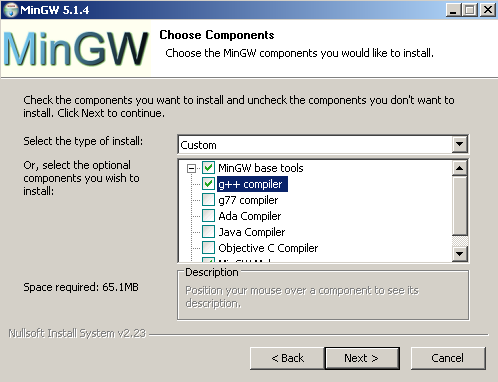
1) First of all, get the MinGW C++ compiler installed. Make sure you check the g++ compiler, which is actually the C++ compiler we are looking for! The other compilers you can leave unchecked. See the picture below.
2) Extract the Development Library of SDL (SDL-devel-1.2.14-mingw32.tar.gz or newer).
3) Among other things there should be one folder called “lib” within the newly created folder of step 2. Copy the complete content of folder “lib” (3 files) into a folder also named “lib” in the MinGW directory. Make sure only to copy these three files, not the folder “lib” itself.
4) There is also a folder “include” in the extracted SDL Development Library folder. It contains one further folder called “SDL” (contains 34 files). This time copy this folder “SDL” as a whole into the “include” folder of the MinGW installation.
5) Now MinGW is fully prepared for the compiling of SDL_GFX.
6) Extract now the source code of SDL_GFX (SDL_gfx-2.0.22.tar.gz or newer).
7) Within the newly created folder you find a folder called “Other Builds”. Enter this folder. Within this folder you will find several zip files.
8) Extract file “mingw.zip”. This creates a new folder “mingw” and contains exact two files, “Makefile” and “README”.
9) Copy “Makefile” into the root folder of SDL_gfx.
10) Before using this makefile some changes have to be applied. The following script shows the first few lines of the makefile. The bold red printed parts have to be changed according to your needs. [REMARK: Now the lines are marked.]
11) “c:/dev/local” has to be the path to the MinGW root folder [Line 5]. Remove flag “-DWIN32” [Line 10] and change the include flag/path to the corresponding (MinGW root folder)/include/SDL [Line 10, “-I(your path)/include/SDL”]. By the way, make sure to use slashes “/” instead of backslashes “\” to separate folders. Also give the library path as (MinGW root folder)/lib [Line 11, “-L(your path)/lib”]. Now save this makefile.
12) To compile the DLL file now, open the command window of Windows by using Start–>Run…, there type “cmd” and the n “OK”. A new “DOS-like” window will pop up.
12) Change the directory to the SDL_GFX root folder by using the DOS commands “cd (foldername)” and “cd..” to enter or leave a folder.
13) Now just give the full path to the MinGW make program located at “(MinGW root folder)\bin\mingw32-make”. Now press enter and see how your DLL file gets compiled.
14) If everything worked well you find a brand new SDL_gfx.dll in your SDL_GFX root folder.
15) Copy this file to your WINDOWS\system32 folder or to the folder where the application is located which is using SDL_GFX.
Now, since compilation is finished (or you skipped the compilation procedure) just a short hint about the licensing, SDL_GFX is licensed under the LGPL, which essentially means you can also use it in proprietary software.
Before proceeding make sure Free Pascal finds the SDL and SDL_GFX units (Options–>Directories…), however, if you installed a recent binary Free Pascal package you don’t have to care about this. Free Pascal then is already well configured to work with SDL and SDL_GFX.
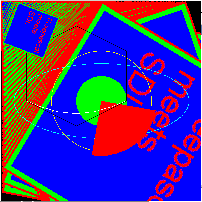
Now we can proceed to the source code. Here is the full source code of the example program. It will rotate and at the same time zoom an image constantly and additionally draw some primitives to the screen.
PROGRAM chap4a;
USES SDL, SDL_GFX, CRT;

CONST
x_array:ARRAY[0..5] OF SINT16 = (50, 150, 250, 250, 150, 50);
y_array:ARRAY[0..5] OF SINT16 = (100, 50, 100, 200, 250, 200);

VAR
screen,original_image,modified_image:pSDL_SURFACE;
angle_value, zoom_value:DOUBLE;
framerate:pFPSMANAGER;
calc_width, calc_height:LONGINT;

BEGIN
SDL_INIT(SDL_INIT_VIDEO);
screen:=SDL_SETVIDEOMODE(400,400,32,SDL_SWSURFACE);
IF screen=NIL THEN HALT;

original_image:=SDL_LOADBMP('C:\FPC\2.2.2\bin\i386-win32\test\fpsdl.bmp');
IF original_image=NIL THEN HALT;

NEW(modified_image);
angle_value:=0.0;
zoom_value:=0.0;

NEW(framerate);
SDL_INITFRAMERATE(framerate);
SDL_SETFRAMERATE(framerate, 30);

REPEAT
  angle_value:=angle_value+1.0;
  zoom_value:=zoom_value+0.05;
  IF angle_value>=359 THEN angle_value:=0.0;
  IF zoom_value>=2.0 THEN zoom_value:=0.0;

  ROTOZOOMSURFACESIZE(400, 400, angle_value, zoom_value, calc_width, calc_height);
  WRITELN('Width: ',calc_width,' Height: ',calc_height);
  modified_image:=ROTOZOOMSURFACE(original_image, angle_value, zoom_value, 1);

  CIRCLECOLOR(screen, 200, 200, 100, $FFFF00FF);
  FILLEDCIRCLECOLOR(screen, 200, 200, 50, $00FF00FF);
  ELLIPSECOLOR(screen, 200, 200, 175, 75, $00FFFFFF);
  FILLEDPIECOLOR(screen, 200, 200, 110, 10, 100, $FF0000FF);
  POLYGONCOLOR(screen, @x_array[0], @y_array[0], 6, $000000FF);
  BEZIERCOLOR(screen, @x_array[3], @y_array[3], 3, 2, $FFFFFFFF);


  SDL_BLITSURFACE(modified_image,NIL,screen,NIL);
  SDL_FLIP(screen);

  SDL_FRAMERATEDELAY(framerate);
UNTIL keypressed;

SDL_FREESURFACE(original_image);
SDL_FREESURFACE(modified_image);
SDL_FREESURFACE(screen);

DISPOSE(framerate);

SDL_QUIT;
END.
Now that you know the whole code, let’s discuss it step by step.
PROGRAM chap4a;
USES SDL, SDL_GFX, CRT;

CONST
x_array:ARRAY[0..5] OF SINT16 = (50, 150, 250, 250, 150, 50);
y_array:ARRAY[0..5] OF SINT16 = (100, 50, 100, 200, 250, 200);

VAR
screen,original_image,modified_image:pSDL_SURFACE;
angle_value, zoom_value:DOUBLE;
framerate:pFPSMANAGER;
calc_width, calc_height:LONGINT;
The program is called “chap4a” and uses the known units SDL and CRT (CRT for easy recognition of user pressing a key on the keyboard). Additionally the new unit SDL_GFX has to be included here. The latter unit provides the functionality described below.
There is a constant block defining two constant arrays “x_array” and “y_array” containing six elements of SINT16 (16 bit signed integer) corresponding to six x and y values. These will be needed later to define a polygon and a Bézier curve.
Three surface variables are defined. The “screen” variable represents the screen surface. The “original_image” surface stores an image, which then is manipulated (rotation and zooming) and the result is stored in the “modified_image” surface. The float number variables “angle_value” and “zoom_value” are storing a certain rotation angle and a zoom factor. Finally variable “framerate” is defined as a framerate manager variable pFPSMANAGER which is new and provided by SDL_GFX. This helpful tool is discussed in much detail later. Finally two variables “calc_width” and “calc_height” are defined and have to be of type LONGINT. They will store the estimated new size of the surface after rotation and zooming.
BEGIN
SDL_INIT(SDL_INIT_VIDEO);
screen:=SDL_SETVIDEOMODE(400,400,32,SDL_SWSURFACE);
IF screen=NIL THEN HALT;

original_image:=SDL_LOADBMP('C:\FPC\2.2.2\bin\i386-win32\test\fpsdl.bmp');
IF original_image=NIL THEN HALT;

NEW(modified_image);
angle_value:=0.0;
zoom_value:=0.0;
The “screen” surface is initialized as known from previous chapters with 400 x 400 px. The “Free Pascal-meets-SDL” bitmap image from Chapter 3 is loaded to the surface variable “original_image”. For those who don’t remember the image, here it is again:
download (right click and “save as”)
Notice, this image has 200 x 200 dimension. The “original_surface” surface will be the source for any manipulation. The second surface “modified_image” gets some space allocated and is ready for usage. However until now it stays empty. The rotation angle and the zoom factor are set to zero.
The framerate manager “framerate” gets some space and is initialized by PROCEDURE SDL_INITFRAMERATE(manager:PFPSmanager). Then the framerate is set in Hz (Hertz) by FUNCTION SDL_SETFRAMERATE(manager:PFPSmanager; rate:INTEGER):INTEGER which returns 0 on success and -1 if something is wrong. The default value is 30 Hz. It is also stored in flag FPS_DEFAULT. Additionally there are FPS_UPPER_LIMIT and FPS_LOWER_LIMIT which correspond to 200 and 1 Hz. Not shown in the example code is FUNCTION SDL_GETFRAMERATE(manager:PFPSMANAGER):INTEGER which will just return the set FPS value, however it will not return the real framerate. Even if the framerate dropped to 1 Hz it will return 30 Hz since this is the set value.
Well, some notes about the framerate: The framerate is usually a value indicating how many frames per second are drawn and shown at the screen. 30 Hz means there are 30 frames drawn to the screen within one second. Often the frequency if abbreviated by FPS meaning Frames Per Second, thus 30 FPS is the same as 30 Hz. If you perform many drawing operation or costly drawing operations (especially 3d applications know this) then it might be that the framerate drops because the system (processor and/or graphic hardware) isn’t capable of drawing fast enough to keep 30 frames per second.
So what about the framerate manager, how does it help? In simple programs the SDL_DELAY(delay in milli seconds) function is used to control the framerate if placed in the rendering loop (the loop which flips the scene to the screen surface). Assuming you set is to 33, so SDL_DELAY(33) it means every 33 ms one frame is drawn, this means approximately 30 frames are drawn within one second! Thus the framerate is 30 Hz here as well. However this only applies if you assume that the drawing itself doesn’t need time, which is a good approximation for simple applications and simple scenes. When drawing more complex scenes the drawing itself will take some milli seconds or even more time, the SDL_DELAY function will just add its delay time, so this leads to a remarkable delay. In contrast a framerate manager recognizes that the framerate dropped and will skip the delay time to keep the framerate at 30 Hz (or whatever value is set). Additionally the framerate manager is keeping the actual framerate more accurately at the framerate, in the contrary SDL_DELAY is quite inaccurate.
REPEAT
  angle_value:=angle_value+1.0;
  zoom_value:=zoom_value+0.05;
  IF angle_value>=359 THEN angle_value:=0.0;
  IF zoom_value>=2.0 THEN zoom_value:=0.0;

  ROTOZOOMSURFACESIZE(400, 400, angle_value, zoom_value, calc_width, calc_height);
  WRITELN('Width: ',calc_width,' Height: ',calc_height);
  modified_image:=ROTOZOOMSURFACE(original_image, angle_value, zoom_value, 1);
Now the rendering loop is entered. Every cycle the rotation angle is increased by 1.0 degree. Also the zoom factor is increased by 0.05 every cycle. A zoom factor of 1.0 means no change of the picture. Values smaller than 1.0 mean shrinkage of the image, values larger than 1.0 mean enlargement of the image. A value of 0.5 and 2.0 mean half the size and double the size of the original image respectively. The two IF clauses ensure that the value of “angle_value” is restored to 0 (equals 360) degree (no rotation), if the image is rotated by 259 degree. If the image got zoomed to twice its original size, “zoom_value” gets restored to 0.0.
PROCEDURE ROTOZOOMSURFACESIZE(width:INTEGER; height:INTEGER; angle:DOUBLE; zoom:DOUBLE; VAR dstwidth:INTEGER; VAR dstheight:INTEGER) calculates the new surface size after rotation and zooming. The first two parameters are the width and height of the initial surface (in our example the image/surface has 200 x 200 dimension). The next two parameters expect the rotation and zoom values (in our example they are stored in “rotation_angle” and “zoom_angle”). The last two parameters store the return values. The results will be returned to “calc_width” and “calc_height” in our example. They are written to the screen. Now one of the most amazing functions of the SDL_GFX unit is introduced. It allows the rotation and zooming of an image. In FUNCTION ROTOZOOMSURFACE(src:pSDL_SURFACE; angle:DOUBLE; zoom:DOUBLE; smooth:INTEGER):pSDL_SURFACE you give the source surface first, which is the surface with the original image in our case, then the angle and zoom factor which we discussed right before and finally if antialiasing should be performed. Antialiasing means to smooth edges. 0 means no antialiasing, 1 means antialiasing, well, also two flags you could use, SMOOTHING_OFF and SMOOTHING_ON. (However I experienced that antialiasing didn’t work out even though a 32 bit surface is used which is necessary to perform antialiasing as the author stated.)
There are some accompied functions not demonstrated in the example code which should be mentioned now. FUNCTION ZOOMSURFACE(src:pSDL_SURFACE; zoomx:DOUBLE; zoomy:DOUBLE; smooth:INTEGER):pSDL_SURFACE zooms only without rotation but zooming in x direction and y direction can be set independently. FUNCTION ROTOZOOMSURFACEXY(src:pSDL_SURFACE; angle:DOUBLE; zoomx:DOUBLE; zoomy:DOUBLE; smooth:INTEGER):pSDL_SURFACE is the same function as before but with rotation additionally. For both of these functions also corresponding procedures exist which return the size of the newly created surfaces. Thay are PROCEDURE ZOOMSURFACESIZE(width:INTEGER; height:INTEGER; zoomx:DOUBLE; zoomy:DOUBLE; VAR dstwidth:INTEGER; VAR dstheight:INTEGER) and PROCEDURE ROTOZOOMSURFACEXYSIZE(width:INTEGER; height:INTEGER; angle:DOUBLE; zoomx:DOUBLE; zoomy:DOUBLE; VAR dstwidth:INTEGER; VAR dstheight:INTEGER). They work the very same way as demonstrated in the example code.
It is very important to keep in mind that every manipulating procedure (rotation and zooming) is distorting the image information. So the number of manipulations should be keep as small as possible. In the example every cycle of the loop the original image gets manipulated exactly two times. It gets rotated once and zoomed once. Instead of this you could also implement a recursive solution, namely rotating the original image in the first cycle by one degree, take the resulting image and rotate it in the second cycle again by one degree, and so on. Let’s check for the result after 25 cycles, in fact both methods rotated the image by 25 degree, but well, the quality is remarkable different. And this neglecting the zooming which has an even worse impact on quality if implemented recursively. The following drawing will illustrate what the results will look like. On the left the rotation of the original image by 25 degree once, on the right the rotation of the same image 25 times by one degree.
Left: Rotation once by 25 degree; Right: 25 Rotations by one degree
The loss of information with each cycle will add up for each manipulation leading to ugly results like the right one. Compare this to the left image where no loss of information is noticable.
As promised SDL_GFX is able to draw a lot of primitives. The primitives shown in the example code are just a few of them. The principle of implementing them is demonstrated anyway. The table below gives the complete list of primitives you can use. Most of the functions are intuitive, so a circle is defined by its position (x/y values), its radius r and its colour. The same applies for a filled circle. An ellipse is defined by its position (x/y values), its horizontal and vertical axes rx and ry, and its colour.
Especially polygon and Bézier curve calls may be not so intuitive. The polygon function is function POLYGONCOLOR(dst:pSDL_SURFACE; const vx:pSINT16; const vy:pSINT16; n:INTEGER; color:UINT32):INTEGER and the Bézier curve function is function BEZIERCOLOR(dst:pSDL_SURFACE; const vx:pSINT16; const vy :pSINT16; n:INTEGER; s:INTEGER; color:UINT32):INTEGER. As for all the other functions you define the surface first onto which you would like to draw these primitives. The next parameters expect a pointer (pSINT16) to an array of x values of type SINT16 (16 bit unsigned integer) and an array of y values of the same type. This is achieved by the @ operator at the first and fourth element of the arrays respectivly. These vectors were defined initially in the constant block, you should remember. The next parameter n is the number of points the polygon has or the number of reference points the Bézier curve has. If the arrays contain six elements, n should be six as well. Since in the case of the Bézier curve only the last three elements are of interest (at least in our example), n has to be three and the resulting curve is of order four (quadratic Bézier curve). The s value defines the smoothness of the curve. The higher s the higher the smoothness.
Some general information about these primitive functions: All functions presented here have the same suffix …COLOR. This means that the last parameter expects the colour you desire in hexadecimal form, $RRGGBBAA. The hexadecimal digit 00 corresponds to decimal digit 0, and hexadecimal digit FF corresponds to decimal digit 255. All of these function are accompanied by a function with the suffix …RGBA instead of …COLOR. Here, all parameters are the same except from the colour parameter, instead of ONE colour code in hexadecimal form, you enter four parameters r, g, b, a (red, green, blue, alpha/transparency). For example instead of $FF0000FF you put 255, 0, 0, 255. All functions return 0 as INTEGER value on success.
In many cases there are further accompanied functions with the prefix aa. This means the very same function with the same parameter list but the result is antialiased. For many functions furthermore the prefix filled is possible as shown for the circle in the example code. Also here the parameter list is completely the same but the resulting primitive is filled with the given colour.
  SDL_BLITSURFACE(modified_image,NIL,screen,NIL);
  SDL_FLIP(screen);

  SDL_FRAMERATEDELAY(framerate);
UNTIL keypressed;
Primitive
Definition
Description
Of all functions two types exist: …Color and …RGBA. They are in fact equal and differ only in the way you put in the colour information. For …Color functions there is the color:Uint32 argument where you put in the colour code in hexadecimal form, e.g. $FF0000FF for red without transparency. For …RGBA functions there are four arguments r:Uint8; g:Uint8; b:Uint8; a:Uint8 where you enter 255; 0; 0; 255 for red without transparency.
Functions with the prefix aa are equal to the functions without this prefix but are printing antialiased primitives. Functions with the prefix filled are equal to the functions without this prefix but the enclosed area of the primitive is filled with the given colour. Antialiased primitives are never filled and vice versa.
All functions return 0 as INTEGER on success.
Pixel (Dot)
function pixelColor( dst : PSDL_Surface; x : Sint16; y : Sint16; color : Uint32 ) : integer
Draws one pixel at position (x/y) in the given colour.
function pixelRGBA( dst : PSDL_Surface; x : Sint16; y : Sint16; r : Uint8; g : Uint8; b : Uint8; a : Uint8 ) : integer
Line
function hlineColor( dst : PSDL_Surface; x1: Sint16; x2 : Sint16; y : Sint16; color : Uint32 ) : integer
Draws a horizontal line from x1 to x2 at height y in the given colour.
function hlineRGBA( dst : PSDL_Surface; x1: Sint16; x2 : Sint16; y : Sint16; r : Uint8; g : Uint8; b : Uint8; a : Uint8 ) : integer
function vlineColor( dst : PSDL_Surface; x : Sint16; y1 : Sint16; y2 : Sint16; color : Uint32 ) : integer
Draws a vertical line at position x from y1 to y2 in the given colour.
function vlineRGBA( dst : PSDL_Surface; x : Sint16; y1 : Sint16; y2 : Sint16; r : Uint8; g : Uint8; b : Uint8; a : Uint8 ) : integer
function boxRGBA( dst : PSDL_Surface; x1 : Sint16; y1 : Sint16; x2 : Sint16;
y2 : Sint16; r : Uint8; g : Uint8; b : Uint8; a : Uint8 ) : integer
Circle
function circleColor( dst : PSDL_Surface; x : Sint16; y : Sint16; r : Sint16; color : Uint32 ) : integer
Draws a circle with the center at position (x/y) and the radius r in the given colour.
function circleRGBA( dst : PSDL_Surface; x : Sint16; y : Sint16; rad : Sint16; r : Uint8; g : Uint8; b : Uint8; a : Uint8 ) : integer
function aacircleColor( dst : PSDL_Surface; x : Sint16; y : Sint16; r : Sint16; color : Uint32 ) : integer
function aacircleRGBA( dst : PSDL_Surface; x : Sint16; y : Sint16;
rad : Sint16; r : Uint8; g : Uint8; b : Uint8; a : Uint8 ) : integer
function filledCircleColor( dst : PSDL_Surface; x : Sint16; y : Sint16; r : Sint16; color : Uint32 ) : integer
function filledCircleRGBA( dst : PSDL_Surface; x : Sint16; y : Sint16;
rad : Sint16; r : Uint8; g : Uint8; b : Uint8; a : Uint8 ) : integer
Pie
function pieColor( dst : PSDL_Surface; x : Sint16; y : Sint16; rad : Sint16;
start : Sint16; finish : Sint16; color : Uint32 ) : integer
Draws a pie chart with the pie’s edge being at position (x/y) with the radius rad. “start” and “finish” define the arc length of the pie in degree. If “start” is 0 then the pie starts at the right (east) side of a circle. To start at the top, “start” should be 270 or -90. If “start” is 0 and “finish” is 90, you get one quarter of a circle.
function pieRGBA( dst : PSDL_Surface; x : Sint16; y : Sint16; rad : Sint16;
start : Sint16; finish : Sint16; r : Uint8; g : Uint8; b : Uint8; a : Uint8 ) : integer
function filledPieColor( dst : PSDL_Surface; x : Sint16; y : Sint16; rad : Sint16;
start : Sint16; finish : Sint16; color : Uint32 ) : integer
function filledPieRGBA( dst : PSDL_Surface; x : Sint16; y : Sint16; rad : Sint16;
start : Sint16; finish : Sint16; r : Uint8; g : Uint8; b : Uint8; a : Uint8 ) : integer
Ellipse
function ellipseColor( dst : PSDL_Surface; x : Sint16; y : Sint16; rx : Sint16; ry : Sint16; color : Uint32 ) : integer
Draws an ellipse with its center at position (x/y) and the two radii rx and ry for its horizontal and vertical axes in the given colour.
function ellipseRGBA( dst : PSDL_Surface; x : Sint16; y : Sint16;
rx : Sint16; ry : Sint16; r : Uint8; g : Uint8; b : Uint8; a : Uint8 ) : integer
function aaellipseColor( dst : PSDL_Surface; xc : Sint16; yc : Sint16; rx : Sint16; ry : Sint16; color : Uint32 ) : integer
function aaellipseRGBA( dst : PSDL_Surface; x : Sint16; y : Sint16;
rx : Sint16; ry : Sint16; r : Uint8; g : Uint8; b : Uint8; a : Uint8 ) : integer
function filledEllipseColor( dst : PSDL_Surface; x : Sint16; y : Sint16; rx : Sint16; ry : Sint16; color : Uint32 ) : integer
function filledEllipseRGBA( dst : PSDL_Surface; x : Sint16; y : Sint16;
rx : Sint16; ry : Sint16; r : Uint8; g : Uint8; b : Uint8; a : Uint8 ) : integer
function filledTrigonRGBA( dst : PSDL_Surface; x1 : Sint16; y1 : Sint16; x2 : Sint16; y2 : Sint16; x3 : Sint16; y3 : Sint16;
r : Uint8; g : Uint8; b : Uint8; a : Uint8 ) : integer
function polygonColor( dst : PSDL_Surface; const vx : PSint16; const vy : PSint16; n : integer; color : Uint32 ) : integer
Draws a polygon with x values from array of SINT16 in vx. y values are from array of SINT16 in vy. n is the number of edges/points the polygon has.
function polygonRGBA( dst : PSDL_Surface; const vx : PSint16; const vy : PSint16;
n : integer; r : Uint8; g : Uint8; b : Uint8; a : Uint8 ) : integer
function aapolygonColor( dst : PSDL_Surface; const vx : PSint16; const vy : PSint16; n : integer; color : Uint32 ) : integer
function aapolygonRGBA( dst : PSDL_Surface; const vx : PSint16; const vy : PSint16;
n : integer; r : Uint8; g : Uint8; b : Uint8; a : Uint8 ) : integer
function filledPolygonColor( dst : PSDL_Surface; const vx : PSint16; const vy : PSint16; n : integer; color : Uint32 ) : integer
function filledPolygonRGBA( dst : PSDL_Surface; const vx : PSint16;
const vy : PSint16; n : integer; r : Uint8; g : Uint8; b : Uint8; a : Uint8 ) : integer
Bézier curve
function bezierColor( dst : PSDL_Surface; const vx : PSint16; const vy : PSint16; n : integer; s : integer; color : Uint32 ) : integer
Draws a Bézier curve of any order. n is the number of points, well n+1 is the order of the curve then. The x and y values are from arrays of SINT16. The higher value s the smoother the curve gets. s should be 2 at least.
function bezierRGBA( dst : PSDL_Surface; const vx : PSint16; const vy : PSint16;
n : integer; s : integer; r : Uint8; g : Uint8; b : Uint8; a : Uint8 ) : integer
SDL_BLITSURFACE(modified_image,NIL,screen,NIL);
SDL_FLIP(screen);
SDL_FRAMERATEDELAY(framerate);
UNTIL keypressed;
Nothing really new here. The “modified_image” surface with the rotated, zoomed image and the primitives is blitted to the screen surface. The result is flipped to the screen. Then the extensivly discussed framerate manager decides by procedure SDL_FRAMERATEDELAY(manager:PFPSMANAGER) how long actually to wait until the loop is repeated. This procedure replaces the common SDL_DELAY command. The loop is stopped when the user presses any key.
Finally all the used surfaces are free’d and the framerate manager is disposed. SDL is quit and the program finished.
This file contains the source code: chap4a.pas (right click and “save as”)
This file is the executable: chap4a.exe (right click and “save as”)
The final result should look and behave like this: The image fpsdl.bmp is rotated and zoomed continouisly and some primitives (circle, filled circle, ellipse, pie, hexagon, Bézier curve) are drawn onto the image. If you use the pre-compiled exe file make sure to have the image copied to c:\.
[Downloads transferred from old website]
SDL_gfx.dll; The pre-compiled SDL_gfx.dll (Version 2.0.19) for chapter 4a.
SDL_gfx-2.0.19.tar.gz; For license reasons here you can download the source code to compile the SDL_gfx.dll for chapter 4a. However, the most recent version for compilation you will find on the authour’s page.
This is an SDL 1.2 chapter. SDL 1.2 is obsolete since it has been replaced by SDL 2.0. Unless you have good reasons to stay here you may prefer to go for the modern SDL 2.0 :-).
Okay. Maybe you think, why to learn how to display pictures first and then learning about the more basic feature to draw single pixels to the screen? – First of all blitting is one of the key features whereas drawing of single pixels to the screen is quite rarely used in applications and games. Though this chapter will get a little bit longer because several things have to be explained more detailed to impart a fully understanding.
We have to know about the meaning of pixels. The physical screen consists of many small units. Every unit consists itself of three different coloured lights. These colours are red, green and blue. If you mix them (additive) you can get every other colour. For example if you mix red and green you get yellow. For three colours that can be mixed with each other there are eight combinations possible which lead to different colours (RGB, RG, RB, R, GB, G, B, all lights off). Some of you may say RGB (white) and all lights off (black) are no colours. That is right but doesn’t matter here and to keep simpliness I will talk of colours even if I talk of black and white.
Did you get confused? Your screen definitvly has more than eight colours, doesn’t it? The reason is, your screen isn’t just able to switch lights on or off. Besides it is able to differ the intensities of the lights. The more intensity levels you have the more colours you can display. The case that you have eight colours as discussed before means that you just have one intensity level. If your screen is in 8 bit mode every pixel on the screen has the possibility to display 2 power 8 colours. That are 256 different colours. Every of the three lights has therefore a certain amount of different intensity levels. If you have 16 bit mode you have 2 power 16 and that are 65536 colours. Each light therefore has the appropriate amount of intensity levels. Since we prefer 32 bit mode, we have 4.29 billion different colours!
All the examples will be at 32 bit mode. If you want to write directly to the screen surface it is possibly necessary that you lock it before performing direct pixel manipulations. We work in software mode (SDL_SWSURFACE) so we can leave locking the screen surface. However, other modes will require you to lock it. Not shown in the example code you can check it by function SDL_MUSTLOCK(surface:pSDL_SURFACE):BOOLEAN. If it evaluates to FALSE or 0 you don’t need to worry about locking. Otherwise you have to lock the surface by function SDL_LOCKSURFACE(surface:pSDL_SURFACE):INTEGER for direct pixel manipulations. It will return 0 if locking was succesful and -1 if locking failed. After pixel manipulations you have to unlock the surface by procedure SDL_UNLOCKSURFACE(surface:pSDL_SURFACE) straight forward.
Now the whole example code is presented. The goal is to have 200 x 200 pixels wide black surface. A single yellow pixel will start to move from the top-left corner along the surface from left to right and line by line until it reaches the bottom of the surface. It then will restart at the top-left corner.
PROGRAM chap4;
USES CRT, SDL;

VAR
screen:pSDL_SURFACE;
pixellocation:^LONGWORD;
pixelcolor,i:LONGWORD;

BEGIN

SDL_INIT(SDL_INIT_VIDEO);
screen:=SDL_SETVIDEOMODE(200,200,32,SDL_SWSURFACE);
IF screen=NIL THEN HALT;

NEW(pixellocation);
WRITE('Pitch value: ',screen^.pitch DIV screen^.format^.BytesPerPixel);

i:=0;
REPEAT
inc(i); IF i>39999 THEN i:=0;

pixellocation:=screen^.pixels+i;               //delete old pixel
pixelcolor:=SDL_MAPRGB(screen^.format,0,0,0);
pixellocation^:=pixelcolor;


pixellocation:=screen^.pixels+i+1;             //draw new pixel
pixelcolor:=SDL_MAPRGB(screen^.format,255,255,0);
pixellocation^:=pixelcolor;

SDL_FLIP(screen);
SDL_DELAY(5);
UNTIL keypressed;

DISPOSE(pixellocation);
SDL_FREESURFACE(screen);
SDL_QUIT;
END.
Now we will go through the whole code step by step. Especially direct pixel manipulations are often misunderstood by newcomers to SDL.
PROGRAM chap4;
USES CRT, SDL;

VAR
screen:pSDL_SURFACE;
pixellocation:^LONGWORD;
pixelcolor,i:LONGWORD;

BEGIN

SDL_INIT(SDL_INIT_VIDEO);
screen:=SDL_SETVIDEOMODE(200,200,32,SDL_SWSURFACE);
IF screen=NIL THEN HALT;
The program is called chap4. As known from previous chapters unit CRT is needed here for a simple input handling and unit SDL is needed for SDL support. The screen variable is known from previous chapters as well and will contain the content which is displayed at the physical screen later. The pixellocation variable is a pointer type variable indicated by the tilde (^). Furthermore the space it’ll point at needs to be of size for a Longword value. The two variables pixelcolor and i are common Longword variables.
The SDL program is initilized as known and the display surface is of size 200 x 200 px and has 32 bit. Except from the pointer variable pixellocation there is nothing new up to here.
NEW(pixellocation);
WRITE('Pitch value: ',screen^.pitch DIV screen^.format^.BytesPerPixel);

i:=0;
REPEAT
inc(i); IF i>39999 THEN i:=0;
In the first line of this part of the code the pointer pixellocation gets some space by the common Free Pascal function NEW(pointer).
Next the pitch value of the surface is printed. Please note, if you create a surface of a certain width and height the true surface can be a little bit wider. In our example this means you have a window of width and height of 200 pixels displayed but there could be an additional unvisible piece of surface. Maybe its true width is 210, so the moving pixel wouldn’t restart at a new line after 200 cycles but 210 cycles. To solve problems caused by this pitch to the surface you can read the pitch out. The data type pitch will allow you to do this (e.g. screen^.pitch). Unfortunately the pitch is not given in pixels (as the width value) but in bytes so you have to devide its value by the BytesPerPixel value which is for our 32 bit surface format usually 4. This value can be read out by screen^.format^.BytesPerPixel. You will see that in our example the width and the pitch are equal (both 200) which means there is no exceeding surface part.
Counter variable i is set to 0. Then the repeat loop is entered. Variable i is increased by 1 each cycle until it reaches 39999. It controls the position of the dot. When i reaches 39999 exactly 40000 cycles are done and the dot should restart at the top-left corner.
Now it gets interesting.
pixellocation:=screen^.pixels+i;               //delete old pixel
pixelcolor:=SDL_MAPRGB(screen^.format,0,0,0);
pixellocation^:=pixelcolor;
Let’s first consider the second line concerning the colour of pixels. If you want to add colour to a single pixel you need to know the corresponding pixel value defining the colour of it. The function SDL_MAPRGB(format:pSDL_PIXELFORMAT; r:UInt8; g:UInt8; b:UInt8):UInt32 or in short SDL_MAPRGB(pixel format, red, green, blue) will make it easy for you to find it out. Just add the pixel format of the surface which is stored in the surface’s format field. For the example surface the expression is screen^.format. A RGB triple of (0,0,0) will lead to black, all lights off (which is also the background colour of the surface). The expected variable type for the RGB triple values are of UInt8 meaning an unsigned 8 bit integer which corresponds to a Free Pascal Byte type variable with a range from 0 to 255. The function will return an unsigned 32 bit integer (UInt32) value which corresponds Free Pascal’s Longword type variable.
Now we are concerned about the actual allocation of a colour to a specific pixel. Every surface provides the possibility to access its pixels, for example by screen^.pixels. The marker pixels is of type Pointer and points to a certain pixel of the surface. By adding to or substraction from it you can easily access any pixel on the surface. So any pixel’s coordinate on the screen can be accessed by using ONE number instead of a pair of (x,y) values. This is an important concept. The integer value screen^.pixels is pointing at represents the colour of this specific pixel. So, don’t confuse these two values. The value of the pixels pointer itself determines the pixel addressed, the value it is pointing at determines the pixel’s colour. The following diagram may help to explain this.
For our 32 bit surface all the pixels are of size Uint32 (unsigned integer 32 bit which equals Longword). That is why we initially made variable pixellocation of type Pointer which will point at values of size Longword. In the first cycle i has the value of 1. So from the first line we see that pixellocation points at the colour value of the screens first pixel. This pixel is black. In the second line the colour value for a black pixel is generated and given to pixelcolor. The third line allocates the black colour value to the first pixel. This actually doesn’t change anything.
pixellocation:=screen^.pixels+i+1;             //draw new pixel
pixelcolor:=SDL_MAPRGB(screen^.format,255,255,0);
pixellocation^:=pixelcolor;
If you compare these three lines of code with the previous ones you will see just minor differences. In the first line pixelcolor additionally is increased by 1 which means we refer here to the pixel next to the previous one. The pixel colour defined here (line 2) is another one, it is yellow. Therefore red has to be 255, green has to be 255 and blue has to be 0. The third line is identical.
Now you get a clear picture of what actually is happening to get the effect of a moving pixel. For each cycle the yellow pixel from the previous cycle is overdrawn by a black pixel and then the very next pixel is drawn yellow. This leads to the impression of a moving pixel.
SDL_FLIP(screen);
SDL_DELAY(5);
UNTIL keypressed;

DISPOSE(pixellocation);
SDL_FREESURFACE(screen);
SDL_QUIT;
END.
When all pixel manipulations are done the screen has to be refreshed as known by SDL_FLIP. To be able to recognize all the pixel movement the loop has to be slown down by known SDL_DELAY. The loop is left if the user presses a key. Finally the allocated memory of the Pointer variable pixellocation and the screen surface are free’d by known DISPOSE and SDL_FREESURFACE. The SDL system is quit by known SDL_QUIT and the program stopped by END.
This file contains the source code: chap4.pas (right click and “save as”)
This file is the executable: chap4.exe (right click and “save as”)
If you didn’t check the demo03.pas program from last chapter you really should check it now. It demonstrates how you can use the pixel by pixel manipulation to create nice effects and the basis for a simple game.
This file contains the source code: demo03.pas (right click and “save as”)
This file is the executable: demo03.exe (right click and “save as”)
The final result should look and behave like this: You have to look quite carefully to recognize a single yellow pixel moving from the left top corner, line by line down until it reaches the right bottom corner.
This is an SDL 1.2 chapter. SDL 1.2 is obsolete since it has been replaced by SDL 2.0. Unless you have good reasons to stay here you may prefer to go for the modern SDL 2.0 :-).
Okay. Maybe you think, why to learn how to display pictures first and then learning about the more basic feature to draw single pixels to the screen? – In chapter 3 you learned beside displaying a picture how common SDL programs are strctured. Furthermore this chapter will get a little bit longer because several things have to explained more detailed to impart a fully understanding. In chapter 3 that was not necessary.
So here we go. First of all we have to know about the meaning of pixels. The physical screen consists of many small units. Every unit consists itself of three different coloured lights. These colours are red, green and blue. If you mix them (additive) you can get every colour. For example if you mix red and green you receive yellow. For three colours that can be mixed with each other there are eight combinations possible which lead to different colours (RGB, RG, RB, R, GB, G, B, all lights off). Some of you may say RGB (white) and all lights off (black) are no colours. That is right but doesn’t matter here and to keep simpliness I will talk of colours even if I talk of black and white.
Did you get confused? Your screen definitvly has more than eight colours, doesn’t it? The reason is, your screen isn’t just able to put on or off lights. Besides it is in position to differ the intensities of the lights. The more intensity levels you have the more colours you can display. The case that you have eight colours as discussed before means that you just have one intensity level. If your screen is in 8 bit mode every pixel on the screen has the possibility to display 2 power 8 colours. That are 256 different colours. Every of the three lights has therefore a certain amount of different intensity levels. There are the red and the green light with eight intensity levels each and the blue light with four intensity levels. If you have 16 bit mode you have 2 power 16 and that are 65536 colours. Each light therefore must have the appropriate amount of intensity levels.
All the examples will be made in 8 bit mode. If you want to write directly to the screen surface it is possibly necessary that you lock it. We work in software mode (SDL_SWSURFACE) so we can leave locking the screen surface. The screen surface is a RECORD of many different data types. To read or write pixels of or to a surface there is a typ marker called “pixels” which is of pointer type. It points at some pixel of the surface. The location gets allocated to a pointer of WORD, namely “pixellocation” we define.
PROGRAM chap4;
USES crt, SDL, SDL_video;

VAR
screen:pSDL_SURFACE;
pixellocation:^WORD;

BEGIN
CLRSCR;
SDL_INIT(SDL_INIT_VIDEO);
screen:=SDL_SETVIDEOMODE(200,200,8,SDL_SWSURFACE);
if screen=nil then HALT(1);

pixellocation:=screen^.pixels;

readln;
SDL_FREESURFACE(screen);
SDL_QUIT;
END.
It is unknown to us where to the surface it is pointing. This may not matter now; this we will treat later. Before we should allocate a colour to the pixel. Up to now we just have handed over the location to “pixellocation”. Yellow is the pixel colour we want to get. Red has to be 255, green has to be 255 and blue has to be 0 to get yellow. The function SDL_MAPRGB(pixel format, red, green, blue) is used to transform that input values into one longinteger (Uint32) code. The pixel format is given by the screen surface. We will use its pixel format by using screen^.format what contains the pixel format information of the screen surface. The calculated “colour code” is handed over to a new defined variable called “pixelcolor”.
So you have stored the location of the pixel to manipulate in variable pixellocation. You have stored the information of the colour you want to receive in pixelcolor. Eventually you have to allocate the pixel colour to the pointed pixel at the surface. That’s it. Of course we have to update the screen surface after the drawing.
PROGRAM chap4;
USES crt, SDL, SDL_video;

VAR
screen:pSDL_SURFACE;
pixellocation:^WORD;
pixelcolor:WORD;

BEGIN
CLRSCR;
SDL_INIT(SDL_INIT_VIDEO);
screen:=SDL_SETVIDEOMODE(200,200,8,SDL_SWSURFACE);
if screen=nil then HALT(1);

pixellocation:=screen^.pixels;
pixelcolor:=SDL_MAPRGB(screen^.format,255,255,0);
pixellocation^:=pixelcolor;

SDL_UPDATERECT(screen,0,0,0,0);
readln;
SDL_FREESURFACE(screen);
SDL_QUIT;
END.
If you look careful to the screen (when running program) you may see the pixel (left upper corner). After this success we want to see the pixel run along the screen! That will help you understand easily how the positioning of the pixel works, probably better as if I try to explain. We define a repeat-unitl loop what will delete old pixel (colour: black) and write a new one exaktly moved up by one pixel.
PROGRAM chap4;
USES crt, SDL, SDL_video;

VAR
screen:pSDL_SURFACE;
pixellocation:^WORD;
pixelcolor,i:WORD;

BEGIN
CLRSCR;
SDL_INIT(SDL_INIT_VIDEO);
screen:=SDL_SETVIDEOMODE(200,200,8,SDL_SWSURFACE);
if screen=nil then HALT(1);

i:=-1;
REPEAT
inc(i); IF i>39999 THEN i:=0;

pixellocation:=screen^.pixels+i;
pixelcolor:=SDL_MAPRGB(screen^.format,0,0,0);
pixellocation^:=pixelcolor;

pixellocation:=screen^.pixels+i+1;
pixelcolor:=SDL_MAPRGB(screen^.format,255,255,0);
pixellocation^:=pixelcolor;

SDL_UPDATERECT(screen,0,0,0,0);
delay(5);
UNTIL keypressed;

SDL_FREESURFACE(screen);
SDL_QUIT;
END.
So the position which is pointed by pixels pointer is set by adding to or substratcing from the position before. As can be seen in the program the pixel position is increased by one and so is the value of where screen^.pixels pointer is pointing at.
If you create a surface of width and height of 200 pixels as in the example the true surface can be a little bit wider. This means you have a window of width and height of 200 pixels displayed but there is an additional unvisible piece of surface. Maybe its width is 210, so the moving pixel in the last example would restart a few lines before end of window. To solve problems cause by this pitch to the surface you can read it out. The data type pitch will allow you to (e.g. screen^.pitch).
This file contains the source code: chap4.pas (right click and “save as”)
This file is the executable: chap4.exe (right click and “save as”)