This chapter will introduce you on how to combine the SDL library with the famous Open Graphics Library (OpenGL). OpenGL is the first choice when it comes to platform independent 2d and 3d graphic programming. As long as you just want to do 2d programming you can stay with SDL and there is no need to use OpenGL (even though OpenGL is also capable of doing 2d graphics). However, if your project needs 3d graphics you can set up your system for this quite easy using OpenGL in SDL. The main advantages of SDL here are that any other task except the graphics is further done by SDL (e.g. keyboard handling, sound,…) to keep the platform independence and ease. Further the setup of your SDL environment for the usage of OpenGL is very easy (compared to the setup without SDL) AND also is platform independent. Without SDL you would’ve to write different code to set up OpenGL for each operating system.
You need this software:
| Software | Version | Source | Description |
|---|---|---|---|
| OpenGL driver | – | – | Usually your graphic card provides the corresponding OpenGL driver and you don’t have to do anything. And if so it is very likely that version 1.1 is fully supported. However if you are one of the few poor people whose graphic card doesn’t support OpenGL, check the graphic card’s manufacturer’s homepage for OpenGL drivers. |
There is support for some others OpenGL related units, like GLUT (OpenGL Utility Toolkit) which provides a simple windowing application programming interface, GLX (OpenGL Extension to the X Window system) which provides a binding to use OpenGL in X Window windows (Linux), GLEXT (OpenGl Extensions) which provide additional functions since version 1.1 of OpenGL from 1996. I didn’t try out any of the latter mentioned units but if you progress in learning and using OpenGL especially GLEXT might get interesting to you since it provides the up-to-date functionality.
Now following the whole code at once as usual.
PROGRAM chap8;
USES CRT, SDL, GL, GLU;

VAR
userkey:CHAR;
screen:pSDL_SURFACE;
h,hh,th,thh:REAL;

BEGIN
//some calculations needed for a regular tetrahedron with side length of 1
h:=SQRT(0.75); //height of equilateral triangle
hh:=h/2;       //half height of equilateral triangle
th:=0.75;      //height of tetrahedron
thh:=th/2;     //half height of tetrahedron

SDL_INIT(SDL_INIT_VIDEO);

SDL_GL_SETATTRIBUTE(SDL_GL_RED_SIZE, 5);
SDL_GL_SETATTRIBUTE(SDL_GL_GREEN_SIZE, 5);
SDL_GL_SETATTRIBUTE(SDL_GL_BLUE_SIZE, 5);
SDL_GL_SETATTRIBUTE(SDL_GL_DEPTH_SIZE, 16);
SDL_GL_SETATTRIBUTE(SDL_GL_DOUBLEBUFFER, 1);

screen:=SDL_SETVIDEOMODE(640, 480, 0, SDL_OPENGL);
IF screen=NIL THEN HALT;

glCLEARCOLOR(0.0, 0.0, 1.0, 0.0);
glVIEWPORT(0,0,640,480);
glMATRIXMODE(GL_PROJECTION);
glLOADIDENTITY;
gluPERSPECTIVE(45.0, 640.0/480.0, 1.0, 3.0);
glMATRIXMODE(GL_MODELVIEW);
glLOADIDENTITY;
glCLEAR(GL_COLOR_BUFFER_BIT);
glENABLE(GL_CULL_FACE);
glTRANSLATEf(0.0, 0.0, -2.0);

REPEAT
SDL_DELAY(50);

glROTATEf(5, 0.0, 1.0, 0.0);
glCLEAR(GL_COLOR_BUFFER_BIT );

glBEGIN(GL_TRIANGLES);
    glCOLOR3f(1.0, 1.0, 0.0);
    glVERTEX3f(thh, 0.0, 0.0);
    glVERTEX3f(-thh, hh, 0.0);
    glVERTEX3f(-thh, -hh, 0.5);

    glCOLOR3f(0.0, 1.0, 1.0);
    glVERTEX3f(thh, 0.0, 0.0);
    glVERTEX3f(-thh, -hh, -0.5);
    glVERTEX3f(-thh, hh, 0.0);

    glCOLOR3f(1.0, 0.0, 1.0);
    glVERTEX3f(thh, 0.0, 0.0);
    glVERTEX3f(-thh, -hh, 0.5);
    glVERTEX3f(-thh, -hh, -0.5);

    glCOLOR3f(1.0, 1.0, 1.0);
    glVERTEX3f(-thh, -hh, 0.5);
    glVERTEX3f(-thh, hh, 0.0);
    glVERTEX3f(-thh, -hh, -0.5);
glEND;

SDL_GL_SWAPBUFFERS;
UNTIL keypressed;

SDL_QUIT;
END.
What this code will do is to switch to the OpenGL mode of SDL and draw a spinning tetrahedron. When you press a key the program aborts. However, some identifiers mentioned in the code are not related to SDL but OpenGL. Furthermore there are some functions which are related to OpenGL but are provided by SDL. Pure OpenGL identifiers begin with GL_ (e.g. GL_TRIANGLES) or gl (e.g. glCLEARCOLOR) whereas SDL provided OpenGL functions begin with SDL_GL_ (e.g. SDL_GL_SETATTRIBUTE).
PROGRAM chap8;
USES CRT, SDL, GL, GLU;

VAR
userkey:CHAR;
screen:pSDL_SURFACE;
h,hh,th,thh:REAL;

BEGIN
//some calculations needed for a regular tetrahedron with side length of 1
h:=SQRT(0.75); //height of equilateral triangle
hh:=h/2;       //half height of equilateral triangle
th:=0.75;      //height of tetrahedron
thh:=th/2;     //half height of tetrahedron
The program is called “chap8”. We use CRT as known from many former chapters to provide an easy way to recognize if a key got pressed. We need SDL for SDL support. New are the OpenGL units GL and GLU which are both included uncompiled in the JEDI unit package as well as pre-compiled along with the FPC compiler.
We need a variable “userkey” to recognize the user pressing a button. This is unrelated to SDL and OpenGL. The screen variable will display the scene later and is known from every former chapter. Four REAL variables are needed for some calculations regarding a tetrahedron.
The first four lines of code after BEGIN are needed to have some pre-calculated values at hand when it comes to constructing the tetrahedron later. h is the height of a equilateral triangle when each side has the length of one. hh corresponds to the half height meaning the value of h devided by two. th is the height of the tetrahedron (from any of the four possible bases to the corresponding peak) constructed of equilateral triangles. thh means the half value of th. These expressions result just from some geometry (Pythagorean theorem) and aren’t related directly to SDL or OpenGL.
SDL_INIT(SDL_INIT_VIDEO);

SDL_GL_SETATTRIBUTE(SDL_GL_RED_SIZE, 5);
SDL_GL_SETATTRIBUTE(SDL_GL_GREEN_SIZE, 5);
SDL_GL_SETATTRIBUTE(SDL_GL_BLUE_SIZE, 5);
SDL_GL_SETATTRIBUTE(SDL_GL_DEPTH_SIZE, 16);
SDL_GL_SETATTRIBUTE(SDL_GL_DOUBLEBUFFER, 1);

screen:=SDL_SETVIDEOMODE(640, 480, 0, SDL_OPENGL);
IF screen=NIL THEN HALT;
First of all we initialize SDL as known. Attention now: Before setting up the video mode for OpenGL we have to set all needed attributes of the OpenGL environment. If you set them afterwards they won’t be recognized and default values are used by OpenGL. The function to do so is SDL_GL_SETATTRIBUTE(attribute, value). The function returns the integer 0 if setting was successful, -1 otherwise. The corresponding function to read out the set value of an attribute is SDL_GETATTRIBUTE(attribute, value) with the same error checking values. The attribute’s value is written to value. This last function is not used in the code.
The following table (Source: JEDI-SDL documentation) shows all possible attributes which can be set:
| Attribute | Description |
|---|---|
| SDL_GL_RED_SIZE | Size of the framebuffer red component, in bits |
| SDL_GL_GREEN_SIZE | Size of the framebuffer green component, in bits |
| SDL_GL_BLUE_SIZE | Size of the framebuffer blue component, in bits |
| SDL_GL_ALPHA_SIZE | Size of the framebuffer alpha component, in bits |
| SDL_GL_DOUBLEBUFFER | 0 or 1, enable or disable double buffering |
| SDL_GL_BUFFER_SIZE | Size of the framebuffer, in bits |
| SDL_GL_DEPTH_SIZE | Size of the depth buffer, in bits |
| SDL_GL_STENCIL_SIZE | Size of the stencil buffer, in bits |
| SDL_GL_ACCUM_RED_SIZE | Size of the accumulation buffer red component, in bits |
| SDL_GL_ACCUM_GREEN_SIZE | Size of the accumulation buffer green component, in bits |
| SDL_GL_ACCUM_BLUE_SIZE | Size of the accumulation buffer blue component, in bits |
| SDL_GL_ACCUM_ALPHA_SIZE | Size of the accumulation buffer alpha component, in bits |
| Source of table and content: JEDI-SDL documentation. |
Each pixel of the screen contains three different colour components (red, green, blue). We want each pixel’s colour component’s size to be five bits. This is a default value for the colour components. The depth buffer (also called Z-buffer) will get 16 bits of size, also a default value. Finally we allow double buffering. Be careful here. The double buffering for an OpenGL scene is not enabled by the SDL flag SDL_DOUBLEBUF in the video set function but is set by SDL_GL_SETATTRIBUTE(SDL_GL_DOUBLEBUFFER, 1). For any other attributes, its meanings and its values refer to OpenGL tutorials which you find anywhere in the Internet.
screen:=SDL_SETVIDEOMODE(640, 480, 0, SDL_OPENGL);
IF screen=NIL THEN HALT;
The goal is to draw an OpenGL scene within a SDL environment to have access to all the advantages each library provides. So after setting all necessary attributes of the OpenGL scene you have to create a SDL window which is able to display an OpenGL scene. To set up such a window you use the common SDL_SETVIDEOMODE(parameters) function. The first two parameters determine the window’s size as known. The values for the width and the height should be consistent with the values for the OpenGL viewport which will be set later.
The third parameter determining the colour depth of a SDL scene should be ignored and set to 0 if you want to set up an OpenGL scene. The colour depth of an OpenGL scene is set up as shown before with SDL_GL_SETATTRIBUTES(parameters). However, any value different from 0 will not affect the OpenGL scene in any way.
To set up an OpenGL scene successfully you must add the SDL_OPENGL flag as shown. However, you can combine it with any other window appearance flag (e.g. fullscreen, without border, …) by using the logic operator OR as known.
glCLEARCOLOR(0.0, 0.0, 1.0, 0.0);
glVIEWPORT(0,0,640,480);
glMATRIXMODE(GL_PROJECTION);
glLOADIDENTITY;
gluPERSPECTIVE(45.0, 640.0/480.0, 1.0, 3.0);
glMATRIXMODE(GL_MODELVIEW);
glLOADIDENTITY;
glCLEAR(GL_COLOR_BUFFER_BIT);
glENABLE(GL_CULL_FACE);
glTRANSLATEf(0.0, 0.0, -2.0);
The following descriptions regard to pure OpenGL programming. Detailed descriptions you’ll find in any OpenGL tutorial. However, I will give a brief overview over these functions.
glCLEARCOLOR(parameters) sets the background colour used if you call glCLEAR to reset the colour buffer. glCLEARCOLOR(parameters) expects four float point values corresponding the red, blue, green colour and the alpha channel (for transparency). Any value is a number between 0.0 and 1.0 where 0.0 means no addition of the corresponding colour component or transparency and 1.0 full addition of the corresponding colour component or complete transparency. In the example code we set up a completly blue background without transparency.
glVIEWPORT(parameters) sets the viewport of the OpenGL scene. The first two parameters are integer x- and y-values for the actual position in space, 0/0 is the default setting. The lower-left corner of the viewport is therefore at position 0/0 by default. The next two parameters define the width and height of the scene’s projection to the physical screen. Remeber please, these two values should be the same as has been used for the window width and height when using SDL_SETVIDEOMODE(parameters). However, it isn’t forbidden to use different values. We use a width of 640 and height of 480 pixels.
glMATRIXMODE(parameter) sets the matrix which you’d like to manipulate. It allows different parameters. Very common values are GL_PROJECTION and GL_MODELVIEW, further parameters are GL_TEXTURE and GL_COLOR. The following matrix operations (glTRANSLATEf, glROTATEf,…) are applied to the set matrix’ stack. Often this function is followed by glLOADIDENTITY. glLOADIDENTITY replaces the current matrix by the identity matrix. All elements of the identity matrix equal 0 except for the diagonal elements which are 1.
First we need to specify the projection transformation. Therefore we set the matrix mode by parameter GL_PROJECTION. Either we choose a perspective projection that reflects a 3d world, so objects with a great z value appear smaller than objects with a lower z value, or we choose an orthographic projection that reflects a 2d world, so objects will be drawn independently of their z value. The latter mode is usually used for text, menus, buttons, even complete side scrolling 2d games. Since we’d like to render a tetrahedron, we set up a persepctive projection matrix by gluPERSPECTIVE(parameters). The prefix “glu” indicates it’s a function from the OpenGL utilities unit. Instead we also could have used the glFRUSTUM(parameters) function which is part of the core OpenGL unit to generate such a matrix but gluPERSPECTIVE(parameters) makes it easy to get a matrix for distortionless display of the resulting projection. The first parameter is the field of view angle (fovy) in degrees. The second parameter is the aspect, usually the aspect ratio of the window dimensions width/height, here 640/480. The last two parameters are the (positive) z values for the near and far clipping plane of the generated viewing frustum. The generated perspective projection matrix corresponds to a viewing frustum.
Next we have to set up the viewing and modeling transformation. We switch to this matrix mode by GL_MODELVIEW as argument for GL_MATRIXMODE(parameter). We replace the matrix stack with the identity matrix. Now any subsequent matrix operations (glTRANSLATEf, glROTATEf,…) are applied to this matrix. It is replaced by the identity matrix and ready for further manipulations. This mode lets you manipulate the actual objects or models, e.g. a tetrahedron.
The color buffer gets cleared by glCLEAR(GL_COLOR_BUFFER_BIT). Then back-face culling is enabled by GL_ENABLE(GL_CULL_FACE). If you draw e.g. a triangle it has two faces. A front face and a back face. In a tetrahedron consisting of four triangles the inner faces are never seen. To avoid drawing them the back-face culling gets enabled so OpenGL isn’t drawing them. Finally the scene gets translated along the z-axis about -2.0 units by glTRANSLATEf(parameters) with x, y and z as parameters.
REPEAT
SDL_DELAY(50);

glROTATEf(5, 0.0, 1.0, 0.0);
glCLEAR(GL_COLOR_BUFFER_BIT );

glBEGIN(GL_TRIANGLES);
    glCOLOR3f(1.0, 1.0, 0.0);
    glVERTEX3f(thh, 0.0, 0.0);
    glVERTEX3f(-thh, hh, 0.0);
    glVERTEX3f(-thh, -hh, 0.5);

    glCOLOR3f(0.0, 1.0, 1.0);
    glVERTEX3f(thh, 0.0, 0.0);
    glVERTEX3f(-thh, -hh, -0.5);
    glVERTEX3f(-thh, hh, 0.0);

    glCOLOR3f(1.0, 0.0, 1.0);
    glVERTEX3f(thh, 0.0, 0.0);
    glVERTEX3f(-thh, -hh, 0.5);
    glVERTEX3f(-thh, -hh, -0.5);

    glCOLOR3f(1.0, 1.0, 1.0);
    glVERTEX3f(-thh, -hh, 0.5);
    glVERTEX3f(-thh, hh, 0.0);
    glVERTEX3f(-thh, -hh, -0.5);
glEND;

SDL_GL_SWAPBUFFERS;
UNTIL keypressed;

SDL_QUIT;
END.
Don’t be worried. This piece of code looks big but this is just because of the definition of the actual tetrahedron. First the REPEAT loop is entered. Every cycle is delayed by 50 milliseconds by the known SDL_DELAY(time in ms) function. Next the scene gets rotated. This can be achieved by the OpenGL function glROTATEf(parameters). You’ve to pass four arguments. The degree of rotation first, then three values which define the orientation of the axis around which is rotated. A triple (1.0 / 0.0 / 0.0) or (0.0 / 1.0 / 0.0) or (0.0 / 0.0 / 1.0) corresponds to a rotation around a x- or y- or z-axis respectivly. However, by linear combination of all the three components you can orient the rotation axis completly free in 3d space. For the tutorial with each cycle of the loop the tetrahedron is rotated by 5 degrees around the y axis. The color buffer gets cleared so the tetrahedron from the previous cycle disappears before drawing a new one (rotated by 5 degrees).
Now we need to construct the tetrahedron. Such constructions of objects is always done between a glBEGIN and glEND clause. Yes, even C/C++ programmers have to use Pascal’s own best BEGIN/END clause here :). Well, the glBEGIN (geometric primitive type) command needs an argument which defines what type of primitive is drawn. In our case we want to draw triangles, so we use GL_TRIANGLES here. Further common arguments are GL_POINTS, GL_LINES, GL_QUADS and GL_POLYGON, for points, lines, quads and polygons. Depending of this setting the vertices given within the glBEGIN/glEND block are interpreted. If you chose GL_TRIANGLES, three vertices are interpreted to form one triangles. However, for GL_LINES, only two vertices are needed. The first and the second vertex from our example would form one line. The third vertex would be interpreted to be the starting point for a new line, the first vertex of the next triangle block would be used as second point to form the second line and so on. Note, for 3d games usually triangles are used since most graphic cards seem to be optimized to draw them.
A tetrahedron consists of four triangular areas. Each trianglular area has three corners, these corners are called vertices in OpenGL. Within the glBEGIN/glEND clause the code has four blocks, each containing three glVERTEX3f(coordinates) and one glCOLOR3f(RGB components) commands. Each block creates one triangular area of the tetrahedron consisting of 3 vertices. Every triangular area also gets its own colour. For glCOLOR3f(RGB components) you use the three normalized colour codes for the red, green and blue component. 1.0 corresponds to 255 and means full addition of this colour component, 0.0 corresponds to 0 and means no addition of this colour component. As you may have noticed in the example always two colour components are used, e.g. red and green leads to yellow. You may prefer other combinations.
For the actual creation of a geometric primitive, like a triangle, just place the corresponding number of vertices in the 3d space and OpenGL will do the rest. It is important though to consider the order of placing the vertices. The order of placing the vertices determines what will be the front and back of the triangles. If you don’t consider this you may end up with curious results after doing back-face culling as described. Remeber: Back-face culling means, that the back of each primitive isn’t drawn. The way the triangles are created in the examples all areas have their front showing while their back is inside the tetrahedron. So without hestiation you can leave them undrawn. Imagine though what would be the result if one of the triangles would have been flipped because of placing the vertices in the wrong order. The undrawn back would show up. The impression of a rotating tetrahedron would be messed up. To get the front showing up instead of the back you have to place the vertices anticlockwise! The arguments for glVERTEX3f(x, y, z coordinate) are just the cartesian coordinates of the vertex you want to place.
Since I decided to give a rather complicated example for this tutorial (usually OpenGL tutorials explain this by cubes and six quads) I will examine the code here in more detail for the first triangle. If you’ve understood it, you’ll do cubes just by the way :). The coordinates for the first vertex are (thh / 0 / 0), the next vertex are (-thh / hh / 0) and the last vertex are (-thh / -hh / 0.5). The following image will show you how the vertices are placed in the cartesian space.
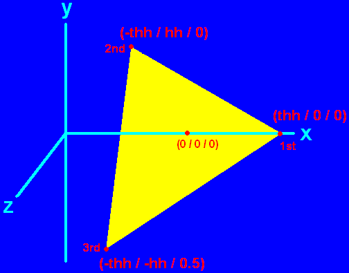 As you can check quickly, the vertices are indeed placed anticlockwise. The origin of the coordinate system (0 / 0 / 0) is approximately in the center of the triangle, actually it is in the center of the tetrahedron, when it is finished. The first vertex is placed onto the x axis at thh, the half height of the tetrahedron. The second vertex is placed on the opposite x position of the origin at -thh and has a y value of hh, the half height of an equilateral triangle. This point is still in the x/y-plane formed by the x and y axis. The last vertex has a x value of -tth and and y value of -hh, because of the z value of 0.5 this vertex doesn’t belong to the x/y-plane the other two vertices belong to. It is in front of this plane. You’ll notice a slight distorted appearance of the triangle for the third vertex, just as if it would bend towards you, that is because it actually is.
Now try to check if you understand the other vertices coordinates and if you understand why their front and not their back is showing. The loop’s last command is SDL_GL_SWAPBUFFERS which corresponds to SDL_FLIP for a pure SDL scene. It refreshes the scene. In case you have an OpenGL scene you never use SDL_FLIP or SDL_UPDATERECT to refresh the scene!
The loop quits if a key gets pressed. Then SDL and the Pascal program quit as known. If you want to learn OpenGL and its capabilities to a more advaced extend you need to read more professional tutorials related to pure OpenGL programming. As a starting point I’d like to mention NeHe Productions’ OpenGL tutorials, because they are professional and provide example code for JEDI-SDL for several lessons.
This file contains the source code: chap8.pas (right click and “save as”)
This file is the executable: chap8.exe (right click and “save as”)
The final result should look and behave like this: A tetrahedron consisting of four different coloured areas (yellow, cyan, magenta and white) is spinning slowly around itself. When pressing a key in the console the show quits.
