This is part 2 of the chapter about event handling. Mouse and window handling is treated here.
Let’s start with the full example code:
program Chapter8_SDL2;
uses SDL2;
var
sdlWindow1: PSDL_Window;
sdlEvent: PSDL_Event;
exitloop: boolean = false;
text1: string = '';
begin
//initilization of video subsystem
if SDL_Init( SDL_INIT_VIDEO ) < 0 then HALT;
sdlWindow1 := SDL_CreateWindow( 'Window1', 50, 50, 500, 500, SDL_WINDOW_SHOWN );
if sdlWindow1 = nil then HALT;
new( sdlEvent );
while exitloop = false do
begin
while SDL_PollEvent( sdlEvent ) = 1 do
begin
write( 'Event detected: ' );
case sdlEvent^.type_ of
//keyboard events
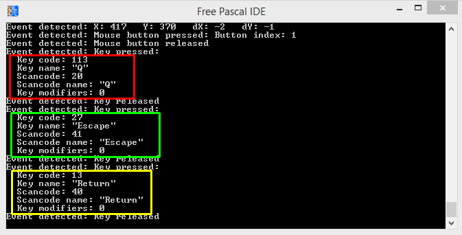
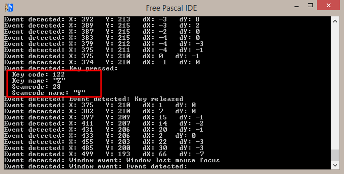
SDL_KEYDOWN: begin
writeln( 'Key pressed:');
writeln( ' Key code: ', sdlEvent^.key.keysym.sym );
writeln( ' Key name: "', SDL_GetKeyName( sdlEvent^.key.keysym.sym ), '"' );
writeln( ' Scancode: ', sdlEvent^.key.keysym.scancode );
writeln( ' Scancode name: "', SDL_GetScancodeName( sdlEvent^.key.keysym.scancode ), '"' );
writeln( ' Key modifiers: ', sdlEvent^.key.keysym._mod );
case sdlEvent^.key.keysym.sym of
27: exitloop := true; // exit on pressing ESC key
//switching text input mode on/off
SDLK_F1: begin
if SDL_IsTextInputActive = SDL_True then SDL_StopTextInput
else SDL_StartTextInput;
writeln(' Text Input Mode switched' );
end;
end;
end;
SDL_KEYUP: writeln( 'Key released ' );
SDL_TEXTINPUT: begin
writeln( 'Text input: "', sdlEvent^.text.text, '"' );
text1 := text1 + sdlEvent^.text.text;
writeln( 'Full string: ' + text1 );
end;
//mouse events
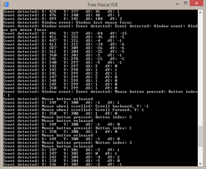
SDL_MOUSEMOTION: begin
writeln( 'X: ', sdlEvent^.motion.x, ' Y: ', sdlEvent^.motion.y,
' dX: ', sdlEvent^.motion.xrel, ' dY: ', sdlEvent^.motion.yrel );
end;
SDL_MOUSEBUTTONDOWN: writeln( 'Mouse button pressed: Button index: ', sdlEvent^.button.button );
SDL_MOUSEBUTTONUP: writeln( 'Mouse button released' );
SDL_MOUSEWHEEL: begin
write( 'Mouse wheel scrolled: ' );
if sdlEvent^.wheel.y > 0 then writeln( 'Scroll forward, Y: ', sdlEvent^.wheel.y )
else writeln( 'Scroll backward, Y: ', sdlEvent^.wheel.y );
end;
//window events
SDL_WINDOWEVENT: begin
write( 'Window event: ' );
case sdlEvent^.window.event of
SDL_WINDOWEVENT_SHOWN: writeln( 'Window shown' );
SDL_WINDOWEVENT_MOVED: writeln( 'Window moved' );
SDL_WINDOWEVENT_MINIMIZED: writeln( 'Window minimized' );
SDL_WINDOWEVENT_MAXIMIZED: writeln( 'Window maximized' );
SDL_WINDOWEVENT_ENTER: writeln( 'Window got mouse focus' );
SDL_WINDOWEVENT_LEAVE: writeln( 'Window lost mouse focus' );
end;
end;
end;
end;
SDL_Delay( 20 );
end;
dispose( sdlEvent );
SDL_DestroyWindow ( sdlWindow1 );
//shutting down video subsystem
SDL_Quit;
end.
Mouse handling in SDL 2.0
If you got the basic concept of event handling, you will find that mouse handling and keyboard handling have a lot in common.
        //mouse events
        SDL_MOUSEMOTION: begin
                           writeln( 'X: ', sdlEvent^.motion.x, '   Y: ', sdlEvent^.motion.y,
                                    '   dX: ', sdlEvent^.motion.xrel, '   dY: ', sdlEvent^.motion.yrel );
                         end;
For mouse motions, mouse buttons and the mouse wheel there are three different mouse event structures: SDL_MouseMotionEvent, SDL_MouseButtonEvent and SDL_MouseWheelEvent.
Mouse motion handling in SDL 2.0
If you are moving the mouse, the SDL_MOUSEMOTION event is triggered. The record structure of the SDL_MouseMotionEvent is shown below:
TSDL_MouseMotionEvent = record
    type_: UInt32;       // SDL_MOUSEMOTION
    timestamp: UInt32;
    windowID: UInt32;    // The window with mouse focus, if any
    which: UInt32;       // The mouse instance id, or SDL_TOUCH_MOUSEID
    state: UInt8;        // The current button state
    padding1: UInt8;
    padding2: UInt8;
    padding3: UInt8;
    x: SInt32;           // X coordinate, relative to window
    y: SInt32;           // Y coordinate, relative to window
    xrel: SInt32;        // The relative motion in the X direction
    yrel: SInt32;        // The relative motion in the Y direction
  end;
Again there are the type_, the timestamp and the windowID fields. Nothing new here. The field which contains the mouse id. This is important if you have more than one mouse device attached to your computer. Think for example of a laptop with a touchpad area to move the mouse cursor and at the same time there is an usb mouse attached to the laptop. To distinguish between the two, you may retrieve their id’s.
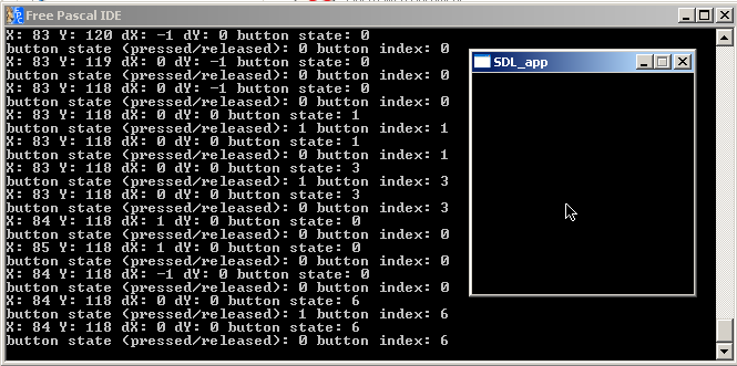
The state field is known from the SDL_KeyBoardEvent structure. It may be a difference if you have a mouse button pressed and move the mouse or if you don’t have a button pressed. The most famous example is if you want to select a bunch of files on your desktop or in a folder. By the way, the state field encodes a number which is different depending on which buttons you pressed actually. This works similar to the key modifiers, if you keep two mousebuttons pressed while moving, the state is the sum of each individual mouse button state value. As an example for my mouse: No mouse button 0, left mouse button 1, right mouse button 4, middle mouse button 2, thumb button 8. If I keep pressed left and right mouse button 5 (sum 1 + 4).
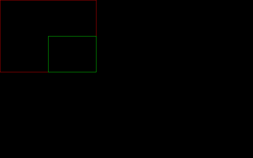
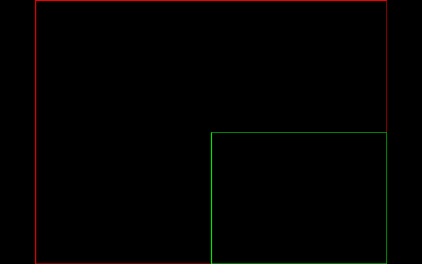
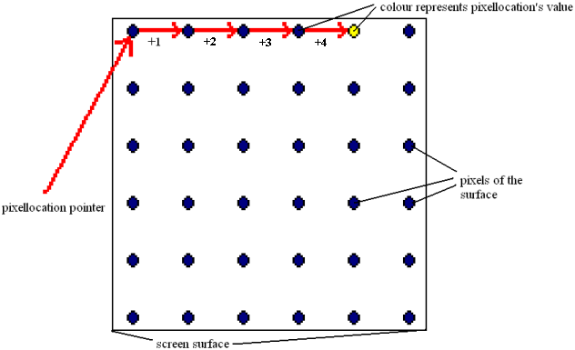
The x and y fields contain the coordinate of the mouse cursor in pixels. These coordinates are relative to the window of the SDL 2.0 application. Keep in mind, the coordinates (0/0) correspond to the left upper corner. Positive x values are counted from left to right and positive y values are counted from top to bottom.
The fields xrel and yrel are used to determine how fast the mouse has been moved from one point to another. Let’s assume you move the mouse surcor from left to right in your application’s window. The first time you do it slowly, xrel might be 1, means, you just moved pixel from left to right between two mouse motion events. If you move fast, xrel might be 50, meaning that this time you moved by 50 pixels between two mouse motion events. Especially for game programming this can be a extremely important information. E.g., think of first person shooter, if the movement speed of the first person view would be independent of the actual movement of the mouse, this game wouldn’t make much sense.
To access these fields the event’s motion field has to be read out. In the example code the (x/y) coordinates and the relative positions xrel and yrel are read out by
sdlEvent^.motion.x
sdlEvent^.motion.y
sdlEvent^.motion.xrel
sdlEvent^.motion.yrel
and simply printed out to the screen. Let’s go for the next chunk of code.
        SDL_MOUSEBUTTONDOWN: writeln( 'Mouse button pressed: Button index: ', sdlEvent^.button.button );
        SDL_MOUSEBUTTONUP: writeln( 'Mouse button released' );
        SDL_MOUSEWHEEL: begin
                          write( 'Mouse wheel scrolled: ' );
                          if sdlEvent^.wheel.y > 0 then writeln( 'Scroll forward, Y: ', sdlEvent^.wheel.y )
                          else writeln( 'Scroll backward, Y: ', sdlEvent^.wheel.y );
                        end;
Pressing a mouse button in SDL 2.0
As for the SDL_KeyBoardEvent, you would want to know if a mouse button and which one is pressed or released. If a mouse button is pressed, a SDL_MOUSEBUTTONDOWN event is triggered. On releasing a mouse button a SDL_MOUSEBUTTONUP event is triggered. It has SDL_MouseButtonEvent structure. Let’s have a look into the structure:
TSDL_MouseButtonEvent = record
    type_: UInt32;       // SDL_MOUSEBUTTONDOWN or SDL_MOUSEBUTTONUP
    timestamp: UInt32;
    windowID: UInt32;    // The window with mouse focus, if any
    which: UInt32;       // The mouse instance id, or SDL_TOUCH_MOUSEID
    button: UInt8;       // The mouse button index
    state: UInt8;        // SDL_PRESSED or SDL_RELEASED
    padding1: UInt8;
    padding2: UInt8;
    x: SInt32;           // X coordinate, relative to window
    y: SInt32;           // Y coordinate, relative to window
  end;
If you compare this structure to the structure of the SDL_MouseMotionEvent, you will find, only the two field xrel and yrel are gone and a new field, a crucial one to be clear, is new, which is button of 8 bit unsigned integer type.
I won’t discuss all the fields again we discussed for the SDL_MouseMotionEvent structure. Attention, if you compare the state field of the SDL_MouseButtonEvent, it works another way. It allows just for two values, SDL_PRESSED or SDL_RELEASED, as known from SDL_KeyBoardEvent. As a reminder: For the SDL_MouseMotionEvent, it represented that full state of all the buttons being pressed while mouse motion.
The button field allows to recognize which button has triggered the SDL_MouseButtonEvent. Each button of the mouse has its own index. As an example for my mouse they are as follows: Left mouse button 1, right mouse button 3, middle mouse button 2, thumb mouse button 4. Do not confuse these index numbers with the mouse button state values of the SDL_MouseMotionEvent structure. There can only be one button which triggered this event! Combinations as for the motion event are not possible. In the example code this value is just printed to the screen using
sdlEvent^.button.button.
You see, to access the fields of this record you need to address the event’s button field. This mustn’t be confused with SDL_MouseButtonEvent’s button field discussed above.
The x and y fields contain the (x/y) coordinates when the mouse button (whose index is stored in field button) has been pressed (or released). This is crucial to know. What would an application be worth if you could recognized that a certain button has been pressed but you don’t know where exactly? Not shown in the code but you could access these fields by
sdlEvent^.button.x
sdlEvent^.button.y.
The mouse wheel in SDL 2.0
If the mouse wheel is used a SDL_MOUSEWHEEL event is triggered. Let’s look into the corresponding SDL_MouseWheelEvent structure.
TSDL_MouseWheelEvent = record
    type_: UInt32;        // SDL_MOUSEWHEEL
    timestamp: UInt32;
    windowID: UInt32;    // The window with mouse focus, if any
    which: UInt32;       // The mouse instance id, or SDL_TOUCH_MOUSEID
    x: SInt32;           // The amount scrolled horizontally
    y: SInt32;           // The amount scrolled vertically
  end;
New fields here are the x and y field which do not correspond to the mouse cursor position this time. Instead of that they refer to the direction of the mouse wheel being scrolled. If you scroll the mouse wheel upwards or forward it will return 1, and if you scroll it backwards it will return -1. If you have a mouse wheel which can be scrolled horizontally, it will be similar. By the way scrolling a mouse wheel can be considered as pressing a button very quickly for that direction.
In the code, if a SDL_MOUSEWHEEL event is triggered, the y value is checked to be positive or negative. This decides if an upward or downward scrolling has happened and the corresponding value (1 or -1) will be returned and printed out. Anyway, could you guess what happens if anyone would use a mouse wheel that is scrolling horizontally? – The same block will be executed since a SDL_MOUSEWHEEL event is triggered. Instead of y being 1 or -1, it will be 0 but the x value will be 1 or -1. Nevertheless, the else-block will be executed since y is not greater than 0. So for the example program it will print out wrongly that an backward scroll has happened. Anyway, you get the idea.
Window handling in SDL 2.0
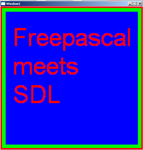
Modern applications are always run in windows. The famous operation system “Windows” by Microsoft even derived it’s name from this. The first task for most of SDL 2.0 applications is the creation of a window. The example code creates a window of width 500 pixels and height 500 pixels. It may be important to know if the user interacts with the application window. Whenever this happens a SDL_WINDOWEVENT is triggered.
        //window events
        SDL_WINDOWEVENT: begin
                           write( 'Window event: ' );
                           case sdlEvent^.window.event of
                             SDL_WINDOWEVENT_SHOWN: writeln( 'Window shown' );
                             SDL_WINDOWEVENT_MOVED: writeln( 'Window moved' );
                             SDL_WINDOWEVENT_MINIMIZED: writeln( 'Window minimized' );
                             SDL_WINDOWEVENT_MAXIMIZED: writeln( 'Window maximized' );
                             SDL_WINDOWEVENT_ENTER: writeln( 'Window got mouse focus' );
                             SDL_WINDOWEVENT_LEAVE: writeln( 'Window lost mouse focus' );
                           end;
If the an event of type SDL_WINDOWEVENT is triggered, the text message “Window event: ” is printed out.
To access the window event fields, you need to access the event’s window field. The field event contains the window event’s type information, hence what window event has been triggered.
sdlEvent^.window.event
In contrast to the keyboard and the mouse event we discussed before, the different event types are not distinguished by the type_ field but by an additional field event.
In the example code six different window event types are checked: SDL_WINDOWEVENT_SHOWN, SDL_WINDOWEVENT_MOVED, SDL_WINDOWEVENT_MINIMIZED, SDL_WINDOWEVENT_MAXIMIZED, SDL_WINDOWEVENT_ENTER and SDL_WINDOWEVENT_LEAVE. From the texts printed out you can guess when they get triggered. I think no further explanation is needed here.
By the way, there are more window event types which are shown a little bit later. Sometimes if one of these is triggered, only the text that a window event has been triggered is shown but without any further details since the example code doesn’t covers further treatment. Feel free to extent the code yourself.
Let’s have a look at the event structure of SDL_WindowEvent.
TSDL_WindowEvent = record
    type_: UInt32;       // SDL_WINDOWEVENT
    timestamp: UInt32;
    windowID: UInt32;    // The associated window
    event: UInt8;        // SDL_WindowEventID
    padding1: UInt8;
    padding2: UInt8;
    padding3: UInt8;
    data1: SInt32;       // event dependent data
    data2: SInt32;       // event dependent data
  end;
The fields type_, timestamp and windowID are known and have the same meaning as discussed before.
The field event stores an identifier (SDL_WindowEventID) to distinguish between different window events. Here they are listed and in brackets you find the window related action which has triggered them:
- SDL_WINDOWEVENT_SHOWN (window has been shown)
- SDL_WINDOWEVENT_HIDDEN (window has been hidden)
- SDL_WINDOWEVENT_EXPOSED (window has been exposed and should be redrawn)
- SDL_WINDOWEVENT_MOVED (window has been moved to data1, data2)
- SDL_WINDOWEVENT_RESIZED (window has been resized to data1xdata2; this is event is always preceded by SDL_WINDOWEVENT_SIZE_CHANGED)
- SDL_WINDOWEVENT_SIZE_CHANGED (window size has changed, either as a result of an API call or through the system or user changing the window size; this event is followed by SDL_WINDOWEVENT_RESIZED if the size was changed by an external event, i.e. the user or the window manager)
- SDL_WINDOWEVENT_MINIMIZED (window has been minimized)
- SDL_WINDOWEVENT_MAXIMIZED (window has been maximized)
- SDL_WINDOWEVENT_RESTORED (window has been restored to normal size and position)
- SDL_WINDOWEVENT_ENTER (window has gained mouse focus)
- SDL_WINDOWEVENT_LEAVE (window has lost mouse focus)
- SDL_WINDOWEVENT_FOCUS_GAINED (window has gained keyboard focus)
- SDL_WINDOWEVENT_FOCUS_LOST (window has lost keyboard focus)
- SDL_WINDOWEVENT_CLOSE (the window manager requests that the window be closed)
This list is based upon information found at the SDL 2.0 wiki.
If you read through the list carefully you will notice the mention of data1 and data2 which rather explains their occurance in the event structure :-)! They need to be read out for SDL_WINDOWEVENT_MOVED and SDL_WINDOWEVENT_RESIZED to get the new window position or dimensions.
At the moment I’m not sure why for window events the distinction between the individual window events (e.g. SDL_WINDOWEVENT_MOVED, SDL_WINDOWEVENT_RESIZED, and so on) is not done by the type_ field as for keyboard, mouse and other events, but rather by the additional event field.
                         end;
      end;
    end;
    SDL_Delay( 20 );
  end;

  dispose( sdlEvent );
  SDL_DestroyWindow ( sdlWindow1 );

  //shutting down video subsystem
  SDL_Quit;

end.
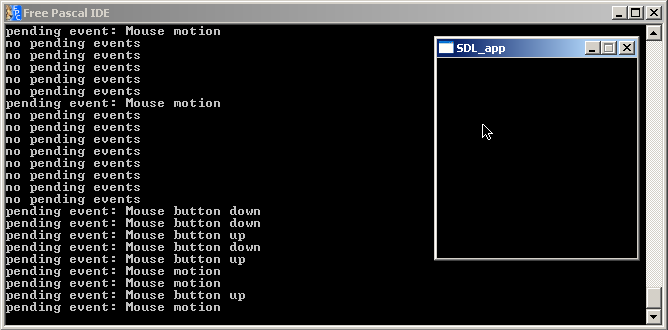
Not much to learn in the final part. The loop is delayed by 20 milliseconds for better recognizability of the text output.
If the loop is left, the event pointer gets free’d, the SDL 2.0 window gets destroyed and SDL 2.0 quit. That’s it :-)!
Touchscreen events, Joystick events and many more!
This chapter covered keyboard, mouse and window events in some detail. Keep in mind, SDL 2.0 has much more to show! – There are many more events you can use for application development. They basically cover any modern type of interaction you could wish for. This includes touchscreen events (important for smartphone development), joystick events (game console development), and even a dropfile event (drag and drop files) and more.
← previous Chapter | next Chapter →